Table of Contents
Advertisement
Quick Links
Installation, Operation
and Maintenance Manual
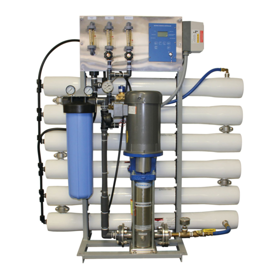
Commercial Reverse Osmosis Systems
Series PWR4021
!
WARNING
Please read carefully before proceeding with
installation. Your failure to follow any attached
instructions or operating parameters may lead to the
product's failure.
Keep this Manual for future reference.
Series PWR4021
IOM-WQ-PWR4021
Advertisement
Table of Contents

Subscribe to Our Youtube Channel
Related Manuals for Watts Pure Water PWR4021 Series


Summary of Contents for Watts Pure Water PWR4021 Series
- Page 1 IOM-WQ-PWR4021 Installation, Operation and Maintenance Manual Commercial Reverse Osmosis Systems Series PWR4021 Series PWR4021 WARNING Please read carefully before proceeding with installation. Your failure to follow any attached instructions or operating parameters may lead to the product’s failure. Keep this Manual for future reference.
-
Page 2: Table Of Contents
Electrical Schematics ........31 this system. Notes Changes in operating variables are beyond the control of Watts. The end user is responsible for the safe operation of this equipment. The suitability of the product water for any specific application is the responsibility of the end user. -
Page 3: Introduction
I. Introduction The separation of dissolved solids and water using RO membranes is a pressure driven temperature dependent process. The membrane material is designed to be as permeable to water as possible while maintaining the ability to reject dissolved solids. The main system design parameters require the following: •... -
Page 4: Pretreatment
C. Pretreatment The RO feed water must be pretreated in order to prevent mem- brane damage and/or fouling. Proper pretreatment is essential for reliable operation of any RO system. Pretreatment requirements vary depending on the nature of the feed water. Pretreatment equipment is sold separately. The most common forms of pretreatment are described below. -
Page 5: Controls, Indicators, And Components
II. Controls, Indicators, and Components (See Figure 1) A. Controller - Controls the operation of the system and displays Product Flow Meter - Indicates the product flow rate in gallons the product water quality. per minute (gpm). Reject Recycle Flow Meter – Indicates the reject recycle flow B. -
Page 6: Controller Drawing - Figure #2 And Figure #3
B. Controller Drawing Figure 2... - Page 7 B. Controller Drawing (continued) Figure 3...
-
Page 8: Operation
III. Operation D. Startup 1. Verify that the pretreatment equipment is installed and working properly. Verify that no free chlorine is present in the feed water. A. Installation 2. Verify that the pump discharge valve (Figure # 1 item D) is open. 1. - Page 9 NOTICE It is very important to vent the mechanical seal during startup. Failure to vent the seal may result in premature seal failure. Vented Priming Plug Back off needle valve to vent air. Retighten to 25 in.-lbs. when vent port runs a steady stream of water.
-
Page 10: Reverse Osmosis Controllers Operation And Maintenance
E. Controllers The controller for this system is the ROC-4 controller. This is a microprocessor-based controller with a product water conductivity meter. A separate manual for this controller begins on the next page. Reverse Osmosis Controller Operations and Maintenance Model #R23-ROC-4 TABLE 1. - Page 11 Figure 4. Simplified Schematic...
- Page 12 Figure 5. Controller Overview Display Keypad (4 line, 20 character) Provides feedback on the System On/Off system status Up Arrow Down Arrow Manual Run, Manual Flush CPU Board Terminal Board Conductivity Programing Probe Port Connections Transformer...
- Page 13 Figure 6. Wiring Diagram Pictorial Schematic of a Typical ROC-4 System...
- Page 14 Figure 7. Controller Detail: CPU-4 Typical Configuration Detailed View Main interface port. Connects via ribbon cable to Terminal Board. BootLoad Switch Used for field updates of CPU-4 firmware Programming Port Standard USB printer cable used for programming. See Appendix B for more about the programming interface Permeate (Optional Feed...
- Page 15 Figure 8. Controller Detail: Terminal Board, TB-3 (See Fig. 3 for schematic) TB24V3...
- Page 16 Figure 9. Conductivity Probe Installation Install the Conductivity Probe in the “Run” Flow of a Tee or equivalent location. Orient the probe so that air cannot become trapped in the area near the probe. Conductivity Probe Flow Input wiring for new “jumper less”...
- Page 17 Installation 1. Drill the enclosure as needed and install liquid-tight fittings for the wiring. 2. Mount the enclosure in the desired location on the RO system. 3. Bring the wires from the peripheral devices into the enclosure and connect them to the appropriate terminals. (See Figures 3,6,7 and 8.) 4.
- Page 18 Figure 10. Controller Programming. Accessing the hidden menus. 1. With the System ON, Press and Hold the UP and DOWN Arrows 2. With the UP and Down Arrows depressed, press the System On/ Off Switch. The menu will switch to the RO Presets menu shown in Figure 10.
- Page 19 TABLE 2. CONTROLLER PROGRAMMING: ROC-4 PROGRAM SELECTIONS The controller has 4 separate user-selectable sets of settings for configuring the RO. The factory default settings are shown below. The settings are identical except for variations in the flush behavior. • Program 1, High Pressure flush. •...
- Page 20 Figure 11. Controller Programming: Menu Navigation...
- Page 21 APPENDIX A. CONTROLLER PROGRAMMING: PARAMETERS EXPLAINED Parameter Value Range Example Input Switch Behaviors Tank Level Switch de-Bounce Seconds 2.0 This specifies the time that the tank switch must be closed or open before the controller accepts it as a valid condition. This helps to prevent nuisance tripping of the RO especially in small or turbulent tanks ...
- Page 22 Controller Fault Condition Displays Below are examples and explanations of the displays which accompany the fault conditions possible in the ROC-4. Fault conditions always indicated a problem of some sort which requires corrective action. The displays provide sufficient information to recognize the source of the fault and the required corrective action.
- Page 23 Appendix B. Controller Programming: Programming Interface Overview The Programming interface is a Windows-based tool for making changes to the ROC software. This screen shows the RO settings available. There are 4 field-selectable sets of settings stored in the CPU-4...
- Page 24 Appendix B. Controller Programming: Programming Interface Overview The WQ screen allows the configuration of the conductivity probes. The status screen shows the input and output status and other operational information.
-
Page 26: Troubleshooting
Troubleshooting RO TROUBLE SHOOTING GUIDE SYMPTOMS Salt Passage Permeate Flow Pressure Drop Location Possible Causes Verification Corrective Action Normal to Decreased Normal to Predominantly Metal oxide Analysis of metal ions in Improved pretreatment to remove metals. increased increased first stage cleaning solution. ... - Page 27 MOTOR TROUBLE SHOOTING CHART TROUBLE CAUSE WHAT TO DO Motor fails to start Blown fuses Replace fuses with proper type and rating. Overload trips Check and rest overload in starter. Improper power supply Check to see that power supplied agrees with motor nameplate and load factor. Open circuit in winding or control switch Indicated by humming sound when switch is closed.
- Page 28 MOTOR TROUBLE SHOOTING CHART (CONTINUED) TROUBLE CAUSE WHAT TO DO Unbalanced line current on polyphase Unequal terminal volts Check leads and connections motors during normal operation Single phase operation Check for open contacts Scraping noise Fan rubbing air shield Remove interference. Fan striking insulation Clear fan.
-
Page 29: Replacement Parts List
7300390 Inlet Solenoid Valve, 1", 24 volt coil with glycerin. 7300817 Watts 4" x 40" RO Membranes 9. Install the end caps and secure them with the retaining plates. 7300923 Package II Controller ROC-4 10. Install the membrane feed hoses. -
Page 30: Appendix
VI. Appendix The following tables are intended as a guide to determining the flow rates for the PWR4021 series RO systems. All flows are in gallons per minute (GPM). Nominal flows for systems with reject recycle and a feed water Silt Density Index less than 3. -
Page 31: Electrical Schematics
Notes... - Page 32 LIMITED WARRANTY: Certain Watts Pure Water products come with a limited warranty from Watts Regulator Co. Other products may have no warranty or are covered by the original manufacturer’s warranty only. For specific product warranty information, please visit www.watts.com or the published literature that comes with your product. Any remedies stated in such warranties are exclusive and are the only remedies for breach of warranty.
Need help?
Do you have a question about the Pure Water PWR4021 Series and is the answer not in the manual?
Questions and answers