Advertisement
Quick Links
sauder.com
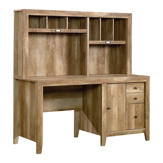
Computer Desk with Hutch
Dakota Pass Collection | Model 420410
Need help? Visit Sauder.com to view video assembly tips or chat with a live rep.
Prefer the phone? Call 1-800-523-3987.
Share your journey!
For all your
newfangled gadgetry.
NOTE: THIS INSTRUCTION
BOOKLET CONTAINS IMPORTANT
SAFETY INFORMATION.
PLEASE READ AND KEEP FOR
FUTURE REFERENCE.
English pg 1-41
Français pg 42-46
Español pg 47-51
Lot # 389671
05/02/16
Purchased: __________________
Be sure to give us a ring before
making any returns. 1-800-523-3987
Advertisement

Related Manuals for Sauder Dakota Pass 420410


Summary of Contents for Sauder Dakota Pass 420410
- Page 1 Dakota Pass Collection | Model 420410 NOTE: THIS INSTRUCTION BOOKLET CONTAINS IMPORTANT SAFETY INFORMATION. Need help? Visit Sauder.com to view video assembly tips or chat with a live rep. PLEASE READ AND KEEP FOR FUTURE REFERENCE. Prefer the phone? Call 1-800-523-3987.
- Page 2 LARGE DRAWER LEFT SIDE (1) CENTER LEG (1) HUTCH BACK LEG (2) D150 DRAWER BACK (1) BACK LEG (3) LARGE DIVIDER (2) D151 LARGE DRAWER BACK (1) HUTCH TOP (1) DIVIDER (2) D953 DRAWER BOTTOM (2) Page 2 420410 www.sauder.com/services...
- Page 3 Now you know Part Identifi cation our ABCs. D150 D953 D151 D953 www.sauder.com/services 420410 Page 3...
- Page 4 DOOR STOP - 1 CONNECTOR - 4 28K KNOB- 4 NAIL - 80 CARD HOLDER - 2 CARD SHEET - 1 CAM COVER - 9 HOLE PLUG - 1 METAL PIN - 20 RUBBER SLEEVE - 4 Page 4 420410 www.sauder.com/services...
- Page 5 15S SILVER 5/8" MACHINE SCREW - 4 30S BLACK 1-9/16" FLAT HEAD SCREW - 8 BLACK 2-1/4" FLAT HEAD SCREW - 15 113S BLACK 1-15/16" FLAT HEAD SCREW - 10 GOLD 1" MACHINE SCREW - 4 www.sauder.com/services 420410 Page 5...
- Page 6 Assemble your unit on a carpeted fl oor or on the empty å carton to avoid scratching your unit or the fl oor. To begin assembly, push a SAUDER TWIST-LOCK® å FASTENER (10F) into the large holes in the ENDS (A and B) and UPRIGHT (E).
- Page 7 HUTCH ENDS (C and D), UPRIGHT (E), TOP (H), and HUTCH TOP (M). Arrow (23 used) Arrow Arrow Hole The arrow in the HIDDEN CAM must point toward the hole in the edge of the board. www.sauder.com/services 420410 Page 7...
- Page 8 Turn twenty-three CAM SCREWS (8F) into the TOP MOLDINGS (EE), å LEGS (I, J, and K), and HUTCH LEGS (V and W). NOTE: Use the exact holes shown. å (23 used) Do not use these holes. Page 8 420410 www.sauder.com/services...
- Page 9 Push the black lever in and pull the SLIDE from the RAIL. GOLD 5/16" FLAT HEAD SCREW (4 used in this step) Open end Edge with TWIST-LOCK® FASTENERS NOTE: The end of this EXTENSION RAIL will set in from the edge of the RIGHT END. Open end www.sauder.com/services 420410 Page 9...
- Page 10 END (A) and the CABINET LEFT (35GB) to the SMALL UPRIGHT (F). Use four GOLD 5/16" FLAT HEAD SCREWS (3S) through holes #1 and #3. GOLD 5/16" FLAT HEAD SCREW (4 used in this step) Roller end Edge with TWIST-LOCK® FASTENERS Roller end Page 10 420410 www.sauder.com/services...
- Page 11 Notched edge Groove Slide the BOTTOM MOLDING (FF) onto the notched edge. Notched edge Slide the LARGE SHELF MOLDING (DD) Notched edge onto the notched edge. Slide the SHELF MOLDING (CC) onto the notched edge. Groove www.sauder.com/services 420410 Page 11...
- Page 12 NOTE: Be sure to position the CARD HOLDERS exactly as shown with the CARD slot å facing the top edges of the MOLDINGS. Card slot Top edge SILVER 5/8" MACHINE SCREW (4 used in this step) Top edge Page 12 420410 www.sauder.com/services...
- Page 13 Angled edge These surfaces should be even. S u r f a c i t h I S T - L O F A S T E N ® E R S Edge with TWIST-LOCK® FASTENERS www.sauder.com/services 420410 Page 13...
- Page 14 E R S These surfaces should be even. S u r f a c i t h I S T - L O F A S T E N ® E R S Edge with TWIST-LOCK® FASTENERS Page 14 420410 www.sauder.com/services...
- Page 15 Fasten the HUTCH RIGHT END (C) to the HUTCH å TOP (M). Tighten two TWIST-LOCK® FASTENERS. Caution ® How to use the SAUDER TWIST-LOCK FASTENER 1. Insert the dowel end of the FASTENER into the hole of the Do not stand the unit upright without the adjoining part.
- Page 16 å insert into the holes in the SHELF (P). Finished edge ® - L O I S T i t h f a c E R S S u r T E N F A S Page 16 420410 www.sauder.com/services...
- Page 17 Use your short screwdriver to tighten these two TWIST-LOCK® FASTENERS. i t h ® f a c S u r - L O I S T E R S Finished edge T E N F A S www.sauder.com/services 420410 Page 17...
- Page 18 S u r - L O I S T I S T E R S - L O T E N ® F A F A S S T E N E R Page 18 420410 www.sauder.com/services...
- Page 19 Flat end CONNECTORS (17F) into the notches in the TOP MOLDINGS (EE). Then, fasten one of the TOP MOLDINGS (EE) å to the HUTCH TOP (M). Tighten four HIDDEN CAMS. Flat end These edges should be even. www.sauder.com/services 420410 Page 19...
- Page 20 TOP MOLDING and HUTCH LEGS once the HIDDEN CAMS are tightened. NOTE: You may need to gently tap the MOLDING CONNECTORS back into the TOP MOLDING and HUTCH LEGS once the HIDDEN CAMS are tightened. Page 20 420410 www.sauder.com/services...
- Page 21 NOTE: You should start each SCREW a few turns before å completely tightening any of them. Edge with holes S u r f a c H I D D E N i t h 113S BLACK 1-15/16" FLAT HEAD SCREW (6 used in this step) www.sauder.com/services 420410 Page 21...
- Page 22 å Tighten three TWIST-LOCK® FASTENERS. i t h K ® f a c L O C S u r I S T - E R S T E N F A S Edge with TWIST-LOCK® FASTENERS Page 22 420410 www.sauder.com/services...
- Page 23 K ® f a c L O C S u r I S T - E R S T E N F A S These TWIST-LOCK® FASTENERS will be tightened in Step 23. www.sauder.com/services 420410 Page 23...
- Page 24 K ® f a c L O C S u r I S T - E R S T E N F A S 113S BLACK 1-15/16" FLAT HEAD SCREW (2 used in this step) Page 24 420410 www.sauder.com/services...
- Page 25 F A S I S T i t h F A S - L O T E N ® E R S 113S BLACK 1-15/16" FLAT HEAD SCREW (2 used in this step) www.sauder.com/services 420410 Page 25...
- Page 26 Fasten the RIGHT END (A) to the TOP (H) and å BOTTOM (N). Tighten four TWIST-LOCK® FASTENERS Fasten the TOP MOLDING (EE) to the TOP (H). Tighten å four HIDDEN CAMS. Edge with holes These edges should be even. Page 26 420410 www.sauder.com/services...
- Page 27 NOTE: You may need to gently tap the MOLDING CONNECTORS back into the TOP MOLDING and å LEGS once the HIDDEN CAMS are tightened. NOTE: You may need to gently tap the MOLDING CONNECTORS back into the TOP MOLDING and LEGS once the HIDDEN CAMS are tightened. www.sauder.com/services 420410 Page 27...
- Page 28 NOTE: Adjustments to the ADJUSTABLE FOOT will be made in Step 25 å once your unit is standing upright. Tighten three TWIST-LOCK® FASTENERS. For support, place packing foam and magazines here. BLACK 9/16" LARGE HEAD SCREW (4 used for the ADJUSTABLE FOOT) Page 28 420410 www.sauder.com/services...
- Page 29 Fasten the top and side edges of the LARGE BACK (R) fi rst. These holes must line up over the SMALL UPRIGHT (F). The BACK (S) overlaps the LARGE BACK (R). NAIL (80 used in this step) www.sauder.com/services 420410 Page 29...
- Page 30 IMPORTANT: The ADJUSTABLE FOOT should not extend å beyond the bottom edges of the LEGS (I, J, K, and L). With your No. 2 Phillips Screwdriver, turn the ADJUSTABLE FOOT downward until it touches the fl oor. Floor Page 30 420410 www.sauder.com/services...
- Page 31 Step Step 26 Fasten the HINGES (40H) to the DOOR (T). Use four å BLACK 1/2" FLAT HEAD SCREWS (11S). BLACK 1/2" FLAT HEAD SCREW (4 used in this step) www.sauder.com/services 420410 Page 31...
- Page 32 Fasten a KNOB (28K) to the DOOR (T). Use a GOLD 1" å Hinge MACHINE SCREW (50S). Insert a DOOR STOP (4I) into the hole in the UPRIGHT (E). å See the next step for DOOR adjustments. å GOLD 1" MACHINE SCREW (1 used for the KNOB) Page 32 420410 www.sauder.com/services...
- Page 33 To adjust the DOORS in or out (depth), loosen the mounting screw å one turn and move the DOORS in or out, as needed. Tighten the mounting screw after making adjustments. Mounting screw (depth) Adjusting screw (horizontal) (vertical adjustment) www.sauder.com/services 420410 Page 33...
- Page 34 D15). Use four BLACK 1-9/16" FLAT HEAD SCREWS (30S). NOTE: Be sure the DRAWER BOTTOM (D953) inserts into the groove of the å LARGE DRAWER BACK (D151). Repeat this step for the other drawer using parts AA, D12, D13, D150, and D953. å Page 34 420410 www.sauder.com/services...
- Page 35 SLIDE. Open end Screw head - turn CAM to line up holes in the SLIDES with holes in DRAWER SIDES Open end (4 screws per drawer) GOLD 5/16" FLAT HEAD SCREW (4 used in this step) www.sauder.com/services 420410 Page 35...
- Page 36 SLIDE. Roller end Screw head - turn CAM to line up holes in the SLIDES with holes in DRAWER SIDES Roller end (4 screws per drawer) GOLD 5/16" FLAT HEAD SCREW (4 used in this step) Page 36 420410 www.sauder.com/services...
- Page 37 Fasten three KNOBS (28K) to the DRAWER FRONTS (AA å and BB). Use three GOLD 1" MACHINE SCREWS (50S). GOLD 1" MACHINE SCREW (3 used for the KNOBS) NOTE: This KNOB will be fastened underneath the DRAWER BOTTOM. www.sauder.com/services 420410 Page 37...
- Page 38 Slide another FILE GLIDE (4B) onto the other end of the FILE RODS (7B), å then press this FILE GLIDE over the LARGE DRAWER LEFT SIDE (D15). Insert the FILE RODS into the holes of your choice in the FILE GLIDES, depending on your fi le sizes. Page 38 420410 www.sauder.com/services...
- Page 39 Push four RUBBER SLEEVES (2R) over four METAL PINS (1R). å Insert the METAL PINS into the hole locations of your choice in the UPRIGHTS (E and F). Set the ADJUSTABLE SHELF (U) onto the METAL PINS. (4 used) www.sauder.com/services 420410 Page 39...
- Page 40 Push the HOLE PLUG (41P) into the hole in the BOTTOM (N). å 15 lbs. (9 used) 15 lbs. total To cover HIDDEN CAMS 15 lbs. total 10 lbs. 60 lbs. 20 lbs. 25 lbs. each Page 40 420410 www.sauder.com/services...
- Page 41 #3. The higher the screw in the oblong hole, the higher your drawer front will be. The lower the screw, the lower the drawer front. www.sauder.com/services 420410 Page 41...
- Page 42 EXTRÉMITÉ DROITE ..........1 35GA ÉLÉMENT DROITE............1 pour future référence. EXTRÉMITÉ GAUCHE ..........1 35GB ÉLÉMENT GAUCHE ...........1 Pour contacter Sauder EXTRÉMITÉ DROITE DE SURMEUBLE ..1 35GC TIROIR DROIT ..............1 en ce qui concerne cet EXTRÉMITÉ GAUCHE DE SURMEUBLE ..1 35GD TIROIR GAUCHE ............1 MONTANT................1...
- Page 43 Enfi ler la MOULURE DE TABLETTE* (CC) sur le chant cranté de la TABLETTE (P). Pour commencer l'assemblage, enfoncer une FIXATION TWIST-LOCK® SAUDER (10F) dans les gros trous des * Brevet État Unis n° 5,499,886 EXTRÉMITÉS (A et B) et le MONTANT (E).
- Page 44 Serrer quatre FIXATIONS TWIST-LOCK®. CONNECTEURS DE MOULURE dans la MOULURE DE DESSUS et les PIEDS DE SURMEUBLE une fois les EXCENTRIQUES Fixer la MOULURE DE DESSUS (EE) sur le DESSUS (H). Serrer ESCAMOTABLES sont serrés. quatre EXCENTRIQUES ESCAMOTABLES. Page 44 420410 www.sauder.com/services...
- Page 45 REMARQUE : De plus, s'assurer de bien enfoncer les CLOUS (1N) dans les trous qui sont alignés sur le MONTANT DE SURMEUBLE (G) et les TABLETTES (P et Q). REMARQUE : Ne pas clouer les clous dans le chant inférieur du GRAND ARRIÈRE à ce point. www.sauder.com/services 420410 Page 45...
- Page 46 Ceci complète l'assemblage. Nettoyer à l’ a ide d’une encaustique pour meubles ou d’un chiff on humide. Essuyer. ÉTAPE 32 Fixer trois BOUTONS (28K) aux DEVANTS DE TIROIR (AA et BB). Utiliser trois VIS À MÉTAUX 25 mm DORÉES (50S). Page 46 420410 www.sauder.com/services...
- Page 47 35GC CAJÓN DERECHO ............1 pour future référence. EXTREMO DERECHO DE ORGANIZADOR ..1 35GD CAJÓN IZQUIERDO ...........1 EXTREMO IZQUIERDO DE ORGANIZADOR ..1 Pour contacter Sauder (JUEGO DE EXTENSIÓN SE MUESTRA POR SEPARADO) PARAL ...................1 en ce qui concerne cet RIEL DE EXTENSIÓN ..........2 PARAL PEQUEÑO ............1...
- Page 48 Para comenzar el ensamblaje, empuje un SUJETADOR TWIST-LOCK® *Patente EE. UU. No. 5,499,886 SAUDER (10F) en los agujeros grandes de los EXTREMOS (A y B) y del PARAL (E). Repita este paso para los EXTREMOS DE ORGANIZADOR (C y D), PASO 7 el PARAL PEQUEÑO (F), el PARAL DE ORGANIZADOR (G), el...
- Page 49 BIELAS DE EXCÉNTRICO de las PATAS en los agujeros de NEGROS DE CABEZA PERDIDA de 49 mm (113S). los EXTREMOS (A y B). NOTA: Debe apretar cada TORNILLO unas vueltas antes de apretar cualquier tornillo fi rmemente. www.sauder.com/services 420410 Page 49...
- Page 50 Apriete el tornillo de montaje después de hacer los ajustes. de los agujeros que se alinean sobre el PARAL PEQUEÑO (F). NOTA: Hay perforaciones provistas para el acceso a través del DORSO. Cuidadosamente corte los agujeros necesarios. Page 50 420410 www.sauder.com/services...
- Page 51 NOTA: Por favor, lea las páginas de atrás del folleto de instrucciones en cuanto a importante información de seguridad. Esto completa el ensamblaje. Limpie con su pulimento para muebles preferido o un paño húmedo. Seque con un paño. www.sauder.com/services 420410 Page 51...
- Page 52 • This product is not designed to support a not designed to support a television is heavy. Plus the weight and location of the television. hazardous. picture tube tends to make TVs unbalanced and prone to tipping forward. Page 52 420410 www.sauder.com/services...
- Page 53 à Les téléviseurs peuvent être particulièrement un téléviseur. cet eff et. lourds. De plus, le poids et l’emplacement du tube image ont tendance à rendre les téléviseurs instables et enclins à tomber vers l’ a vant. www.sauder.com/services 420410 Page 53...
- Page 54 Además, el peso y la ubicación del tubo de imagen tienden a causar la inestabilidad de televisores y propensa a volcarse hacia adelante. Page 54 420410 www.sauder.com/services...
- Page 55 GARANTIE LIMITÉE DE 5 ANS 1. Sauder Woodworking Co. (Sauder®) off re une couverture de garantie limitée à l’ a cheteur 4. La présente garantie ne s’ a pplique qu’ a ux défauts garantis qui se produisent pour initial du présent produit pendant une période de cinq ans à...
- Page 56 Dear Valued Customer: So, how did it go? Thanks so much for choosing Sauder® furniture. I hope the Set a world record for speed? purchase and assembly process was a positive experience Feeling good about yourself? and you feel good about the furniture you just built. If you Nice.
Need help?
Do you have a question about the Dakota Pass 420410 and is the answer not in the manual?
Questions and answers