Advertisement
Quick Links
sauder.com
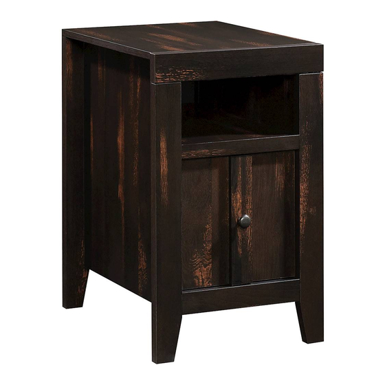
Side Table
Dakota Pass Collection | Model 422593
Need help? Visit Sauder.com to view video assembly tips or chat with a live rep.
Prefer the phone? Call 1-800-523-3987.
Share your journey!
Gets on your couch' s
good side.
NOTE: THIS INSTRUCTION
BOOKLET CONTAINS IMPORTANT
SAFETY INFORMATION.
PLEASE READ AND KEEP FOR
FUTURE REFERENCE.
English pg 1-22
Français pg 23-25
Español pg 26-29
Lot # 506532
07/20/17
Purchased: __________________
Be sure to give us a ring before
making any returns. 1-800-523-3987
Advertisement

Related Manuals for Sauder Dakota Pass 422593


Summary of Contents for Sauder Dakota Pass 422593
- Page 1 Dakota Pass Collection | Model 422593 NOTE: THIS INSTRUCTION BOOKLET CONTAINS IMPORTANT SAFETY INFORMATION. Need help? Visit Sauder.com to view video assembly tips or chat with a live rep. PLEASE READ AND KEEP FOR FUTURE REFERENCE. Prefer the phone? Call 1-800-523-3987.
- Page 2 Assembly Tools Required Part Identifi cation No. 2 Phillips Screwdriver Tip Shown Actual Size Hardware Identifi cation Assembly Steps 5-22 Hammer Not actual size Français 23-25 Español 26-29 Skip the power trip. Safety This time. Warranty Page 2 422593 www.sauder.com/services...
- Page 3 RIGHT END (1) LEFT END (1) TOP (1) SHELF/BOTTOM (2) BACK (1) DOOR (1) RIGHT LEG (1) LEFT LEG (1) BACK LEG (2) SLIDING SHELF (1) TOP MOLDING (1) SHELF MOLDING (1) BOTTOM MOLDING (1) DOOR MOLDING (1) www.sauder.com/services 422593 Page 3...
-
Page 4: Table Of Contents
CAM COVER - 4 3S GOLD 5/16" FLAT HEAD SCREW - 4 BLACK 1/2" FLAT HEAD SCREW - 4 BLACK 1" PAN HEAD SCREW - 6 BLACK 2-1/4" FLAT HEAD SCREW - 4 SILVER 1-1/2" MACHINE SCREW - 1 Page 4 422593 www.sauder.com/services... - Page 5 Assemble your unit on a carpeted fl oor or on the empty å carton to avoid scratching your unit or the fl oor. To begin assembly, push a SAUDER TWIST-LOCK® å FASTENER (7F) into the large holes in the SHELF/ BOTTOMS (D) and SLIDING SHELF (J).
- Page 6 Then, insert the metal end of a CAM DOWEL (2F) into each HIDDEN CAM. Do not tighten the HIDDEN CAMS in this step. Arrow Arrow (4 used) Insert the metal end of the CAM DOWEL into the HIDDEN CAM. Page 6 422593 www.sauder.com/services...
- Page 7 Push four HIDDEN CAMS (1F) into the exact holes shown å in the ENDS (A and B). Arrow Arrow Arrow Hole The arrow in the HIDDEN CAM must point toward the hole in the edge of the board. www.sauder.com/services 422593 Page 7...
- Page 8 Step 4 Turn four CAM SCREWS (8F) into the LEGS (G and H). å NOTE: Be sure to use the exact holes shown in the LEGS. å Page 8 422593 www.sauder.com/services...
- Page 9 CAM DOWELS Edge with HIDDEN CAMS Edge with CAM DOWELS Angled edge S u r f a c H I D D E N i t h These surfaces should be even. Edge with HIDDEN CAMS www.sauder.com/services 422593 Page 9...
- Page 10 Tighten Risk of damage or Arrow injury. HIDDEN CAMS must be completely Arrow Maximum tightened. HIDDEN 210 degrees CAMS that are not completely tightened may loosen, and parts may separate. To Minimum completely tighten: 190 degrees Page 10 422593 www.sauder.com/services...
-
Page 11: Twist-Lock Fastener
Fasten the SHELF/BOTTOMS (D) to the LEFT END (B). å Tighten four TWIST-LOCK® FASTENERS. ® How to use the SAUDER TWIST-LOCK FASTENER 1. Insert the dowel end of the FASTENER into the hole of the adjoining part. NOTE: The dowel end of the FASTENER must remain fully inserted in the hole of the adjoining part while locking the FASTENER. - Page 12 Edge with HIDDEN CAMS o u t w i t h f a c e C A M S u r D E N H I D Maximum Arrow 210 degrees Minimum 190 degrees Page 12 422593 www.sauder.com/services...
- Page 13 *U.S. Patent No. 5,499,886 å Slide the SHELF MOLDING (L) onto the notched edge. Notched edge The groove is closer to this edge. Slide the BOTTOM MOLDING (M) onto the notched edge. The groove is closer to this edge. www.sauder.com/services 422593 Page 13...
- Page 14 Fasten the FRONT LEGS (G and H) to the ENDS (A and B). Tighten å four HIDDEN CAMS. NOTE: Be sure the WOOD DOWELS in the FRONT LEGS insert å into the holes in the ENDS. Flat edge Flat edge Page 14 422593 www.sauder.com/services...
-
Page 15: Gold 5/16" Flat Head Screw
EXTENSION RAIL out to fi nd the other hole that lines up with the hole in the END. Turn a SCREW into this hole. 40NC 40NA Push the black lever in and pull the SLIDE from the RAIL. GOLD 5/16" FLAT HEAD SCREW (4 used in this step) Open end Open end www.sauder.com/services 422593 Page 15... - Page 16 BACK (E). Push on opposite corners of your unit if needed to make it "square". Fasten the BACK (E) to your unit using the NAILS (1N). å NAIL (18 used in this step) Page 16 422593 www.sauder.com/services...
- Page 17 NOTE: You have the option to fasten your DOOR (F) to the å right or left side of your unit. The following steps will show the DOOR being fastened to the left side of your unit. DOOR ON LEFT DOOR ON RIGHT www.sauder.com/services 422593 Page 17...
-
Page 18: Black 1/2" Flat Head Screw
Step 14 Fasten two HINGES (14H) to the DOOR (F). Use four å BLACK 1/2" FLAT HEAD SCREWS (11S). BLACK 1/2" FLAT HEAD SCREW (4 used in this step) Page 18 422593 www.sauder.com/services... -
Page 19: Black 1" Pan Head Screw
Push the DOOR STOP (4I) into the hole in the RIGHT END (A). å See the next step for DOOR adjustments. å BLACK 1" PAN HEAD SCREW (2 used for the DOOR MOLDING) SILVER 1-1/2" MACHINE SCREW (1 used for the KNOB) www.sauder.com/services 422593 Page 19... - Page 20 To adjust the DOORS in or out (depth), loosen the mounting å screw one turn and move the DOORS in or out, as needed. Tighten the mounting screw after making adjustments. Mounting screw (depth) Adjusting screw (horizontal) (vertical adjustment) Page 20 422593 www.sauder.com/services...
- Page 21 F A S L O C T E N K ® E R S This hole should be closer to this edge. Open end Open end BLACK 1" PAN HEAD SCREW (4 used in this step) www.sauder.com/services 422593 Page 21...
- Page 22 And to celebrate, why not share your success story? Click the inner cartridge into place against the black tab. Front Extension Rail Inner cartridge Black tab 40 lbs. 5 lbs. 15 lbs. (4 used) To cover HIDDEN CAMS 30 lbs. Page 22 422593 www.sauder.com/services...
- Page 23 élément et conserver le livret pour future référence. EXTRÉMITÉ DROITE ..........1 (ENSEMBLE DE GLISSIÈRE ILLUSTRÉ À PART) Pour contacter Sauder EXTRÉMITÉ GAUCHE ..........1 40NA GLISSIÈRE D'EXTENSION ........2 en ce qui concerne cet DESSUS ................1 40NC COULISSE D'EXTENSION ........2 élément, faire référence...
- Page 24 Utilisation de la FIXATION TWIST-LOCK® SAUDER Pour commencer l'assemblage, enfoncer une FIXATION 1. Insérer l'extrémité fi letée de la FIXATION dans le trou de la TWIST-LOCK® SAUDER (7F) dans les gros trous dans les pièce attenante. TABLETTES/DESSOUS (D) et de la TABLETTE COULISSANTE (J).
- Page 25 REMARQUE : Prière de lire les informations importantes sur la sécurité fi gurant sur les pages arrière du manuel d’instructions. Ceci complète l'assemblage. Nettoyer à l’ a ide d’une encaustique pour meubles ou d’un chiff on humide. Essuyer. www.sauder.com/services 422593 Page 25...
- Page 26 (JUEGO DE EXTENSIÓN SE MUESTRA POR SEPARADO) et conserver le livret pour future référence. EXTREMO IZQUIERDO ..........1 40NA RIEL DE EXTENSIÓN ..........2 Pour contacter Sauder PANEL SUPERIOR ............1 40NC CORREDERA DE EXTENSIÓN ......2 en ce qui concerne cet ESTANTE/FONDO............2 EXCÉNTRICO ESCONDIDO .......8 élément, faire référence...
- Page 27 Fije el EXTREMO IZQUIERDO (B) al PANEL SUPERIOR (C). Apriete dos EXCÉNTRICOS ESCONDIDOS. Para comenzar el ensamblaje, empuje un SUJETADOR TWIST-LOCK® SAUDER (7F) dentro de los agujeros grandes de Precaución: Riesgo de daños o heridas. Los Excéntricos Escondidos los ESTANTES / FONDOS (D) y del ESTANTE DESLIZANTE (J).
- Page 28 A continuación deslice el cartucho interno del RIEL DE EXTENSIÓN hacia el exterior para encontrar el otro agujero que se alinea con el agujero del EXTREMO. Atornille un TORNILLO dentro de este agujero. Page 28 422593 www.sauder.com/services...
- Page 29 Para ajustar las PUERTAS hacia atrás o hacia adelante (profundidad), afl oje el tornillo de montaje una vuelta y mueva las PUERTAS hacia el interior o hacia el exterior según sea necesario. Apriete el tornillo de montaje después de hacer los ajustes. www.sauder.com/services 422593 Page 29...
- Page 30 Además, el peso y la ubicación del tubo de imagen tienden a causar la inestabilidad de televisores y son propensos a inclinarse hacia adelante. Page 30 422593 www.sauder.com/services...
- Page 31 à compter de la date d'achat la première fois et qui sont signalés à Sauder dans les limites de couverture de la contre tout défaut de matériaux ou de fabrication des composantes de mobilier Sauder.
- Page 32 Dear Valued Customer: So, how did it go? Thanks so much for choosing Sauder® furniture. I hope the Set a world record for speed? purchase and assembly process was a positive experience Feeling good about yourself? and you feel good about the furniture you just built. If you Nice.
Need help?
Do you have a question about the Dakota Pass 422593 and is the answer not in the manual?
Questions and answers