Table of Contents
Advertisement
Quick Links
Advertisement
Table of Contents

Related Manuals for Federal Signal Corporation UltraVoice RF100UX


Summary of Contents for Federal Signal Corporation UltraVoice RF100UX
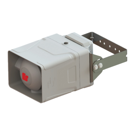
- Page 1 UltraVoice Compact Siren/Speaker ® Models: RF100UX and RF100HX For use in hazardous locations Description, Specifications, Configuration, and Installation Manual 25500705 Rev. A0 0322 Printed in U.S.A. © Copyright 2022 Federal Signal Corporation...
- Page 2 A copy of this limited warranty can also be obtained by written request to Federal Signal Corporation, 2645 Federal Signal Drive, University Park, IL 60484, email to info@fedsig.com or call +1 708-534-3400.
-
Page 3: Table Of Contents
Contents Safety Messages..............................6 Safety Messages to Installers ..........................6 General Description ..............................9 Introduction .................................9 Features ................................9 Commander Software System (SFCDWARE) ....................10 Digital Voice Wizard ............................10 Ordering Information ............................11 Specifications ................................12 Configuration .................................14 Connectors ................................14 Jumpers and Switches ............................15 Site Address Switch–Located on the control board (S1) ...................15 Visual Indicators ..............................16 Radio Interface ..............................16 Programming Functions ............................16... - Page 4 Wiring to the Alarm Initiation Input Connections ....................32 Site Addressing and Encryption Configuration ....................33 Closing the Housing ............................33 Installing the Antenna ............................34 Installing the Antenna Outside Hazardous Locations ................34 Determining the Type of Antenna to Install ....................34 Ordering Replacement Parts ..........................35 Getting Service ..............................35 Tables Table 1 Ordering Information ..........................
- Page 5 Figures Figure 1 Setting the Switch Number Example ....................15 Figure 2 Bracket attached to speaker........................19 Figure 3 Depth and height with bracket ......................20 Figure 4 Back view of speaker ..........................20 Figure 5 Bracket Kit I-IP100-PMW ........................21 Figure 6 Large Pole Mount with Yagi Antenna ....................22 Figure 7 Large Pole Mount with UHF Antenna ....................22 Figure 8 Large Pole Mount with VHF Antenna ....................23 Figure 9 Bracket Kit I-IP100-PM ...........................24...
-
Page 6: Safety Messages
Safety Messages Safety Messages It is important to follow all instructions shipped with this product. This device is to be installed by trained personnel who are thoroughly familiar with the country’s electric codes and will follow these guidelines as well as local codes and ordinances, including any state or local noise-control ordinances. - Page 7 Safety Messages regulations. Perform all work under the direction of the installation or service crew safety foreman. • Read and understand all instructions before installing, operating, or servicing this equipment. • This product shall be mounted at a minimum hearing distance of ten feet per FEMA guidelines limiting sound level exposure to 123 dBc maximum sound level.
- Page 8 Safety Messages EXPLOSION HAZARD: Do not remove or replace fuse when energized. Installation and Service • After installation or service, test the system to confirm that it is operating properly. Test the system regularly to confirm that it will be operational in an emergency. •...
-
Page 9: General Description
General Description General Description Introduction The UltraVoice ® Compact Siren/Speaker (RF100X) is an outdoor or indoor RF-enabled high-powered speaker with an integral controller and radio that can be used in hazardous (classified) locations. The RF100X is part of Federal Signal’s UltraVoice series of products. Use the RF100X as a warning and alerting device with both audible and visual indicators. -
Page 10: Commander Software System (Sfcdware)
General Description • Seven standard built-in warning signals: Wail, Steady, Alternate Wail, Alternate Steady, Pulsed Wail, Pulsed Steady, Auxiliary Chime • Broadcasts live voice and prerecorded voice or tone files • Deliver intelligible voice messages from locally stored prerecorded files or from over- the-air P.A. -
Page 11: Ordering Information
General Description Ordering Information Table 1 Ordering Information Part Numbers Description RF100U Radio Controlled Siren/Speaker with UHF radio RF100H Radio Controlled Siren/Speaker with VHF radio RF100UX Radio Controlled Siren/Speaker with UHF radio for Hazardous Location RF100HX Radio Controlled Siren/Speaker with VHF radio for Hazardous Location Q19902536A Radio Programming Software with USB Interface Cable Kit... -
Page 12: Specifications
Specifications Table 3 YAGI Antenna Kits Part Number Part Number Frequency (with 35 ft cable) (with 10 ft cable) YAGI 1 YAGI 1-10 136-150 MHz YAGI 2 YAGI 2-10 150-174 MHz YAGI 10 YAGI 10-10 450-470 MHz Configuring the RF100X requires Federal Signal Commander ® application software (sold separately). -
Page 13: Table 8 Input And Outputs
Specifications Two Tone Sequential (Not a secure communications method) Frequency range 282-2600 Hz Tone timing First Tone: 0.5 second minimum Second Tone: 0.25 second minimum 8 seconds maximum for both tones Inter-tone Gap 400 ms (maximum) Tone Accuracy +/- 1.5% Tone Spacing 5.0% preferred, 3% minimum Single Tone... -
Page 14: Configuration
Configuration Audible Indications Warning Siren Audio Seven user-configurable tones Pre-recorded files Over 4000 voice or tone messages that total up to 17 hours of recording time Audio Outputs Balanced 24 kΩ 10 V Output 0.2-10.0 V Configuration Connectors The following table provides a description of the RF100X Controller Board connections. Table 9 Connectors AC Solid-State Relay Outputs 1 –... -
Page 15: Jumpers And Switches
Configuration Jumpers and Switches The following table provides a description of the RF100X Controller Board jumpers and switches. Table 10 Configuration Jumpers (Located on the control board.) Disable Digital Receive. Short to disable. Short pins 1 and 2 for stand-alone mode Fast DTMF Decode. -
Page 16: Visual Indicators
Configuration Switch number Binary number Example: Switch numbers 1, 2, and 3 are binary numbers 1, 2, and 4. Add 1 + 2 + 4 = 7; 7 is the unit address NOTE: Programming details are in the software manual. The site address is stored at power up of the controller. -
Page 17: Installation
Installation Installation Read and adhere to all safety warnings in this manual before installing the RF100X. This equipment is suitable for use in Class I, Division 2, Groups A, B, C, D; Class II, Division 2, Groups F and G; Class III or nonhazardous locations only. SOUND HAZARD: The sound output of speakers is capable of causing permanent hearing damage. -
Page 18: Determine The Mounting Method
Installation Determine the Mounting Method The following speaker and antenna mounting options are available for the RF100X. Table 12 Speaker and Antenna Mounting Options Mounting Options Description Flat Wall Mount • A wall-mount bracket is included with the speaker. • The model AMB-W antenna wall mount bracket is available to provide a pipe mount off the surface of the wall. -
Page 19: Attaching The Mounting Brackets To The Speaker Housing
Installation Attaching the Mounting Brackets to the Speaker Housing The RF100X comes standard with a bracket attached for vertical wall or pole mount with optional pole accessories. To attach the bracket to the speaker: The mounting brackets are attached to the speaker, as shown below, using the six supplied 1/4-20 by 5/8-inch screws. -
Page 20: Figure 3 Depth And Height With Bracket
Installation Figure 3 Depth and height with bracket 0.18 6.68 5.88 2.53 10.09 2.00 12.87 Figure 4 Back view of speaker 9.97 5.22 0.16 8.10 0.74 UltraVoice Compact Siren/Speaker (Models RF100UX and RF100HX) ® Federal Signal www.fedsig.com... -
Page 21: Pole Mounting
Installation Pole Mounting The RF100X comes standard with a bracket for vertical wall or pole mount with optional pole accessories. Large Pole Mounting (6-inch diameter or larger) Use the I-IP100-PMW bracket kit for poles that have a diameter of 6 inches or larger. The following figures illustrate typical examples of a pole installation with a bracket and antenna. -
Page 22: Figure 6 Large Pole Mount With Yagi Antenna
Installation Figure 6 Large Pole Mount with Yagi Antenna Utility pole AMB-LP-Y Yagi antenna Bolt for ground wire NOTE: Bands are not included with the kit. Figure 7 Large Pole Mount with UHF Antenna UHF Antenna AMB-LP-U Utility pole Bolt for ground wire NOTE: Bands are not included with the kit. -
Page 23: Small Pole Mounting (2-3/8 Inch To 4-1/2 Inch Diameter Poles)
Installation Figure 8 Large Pole Mount with VHF Antenna VHF Antenna Utility pole AMB-LP-H Bolt for ground wire NOTE: Bands are not included with the kit. Small Pole Mounting (2-3/8 inch to 4-1/2 inch diameter poles) Use the I-IP100-PM bracket kit for poles that have a diameter between 2-3/8 and 4-1/2 inches. -
Page 24: Figure 9 Bracket Kit I-Ip100-Pm
Installation Figure 9 Bracket Kit I-IP100-PM Figure 10 Small Pole Mount with Yagi Antenna Utility pole AMB-SP-Y Yagi antenna Bolt for ground wire UltraVoice Compact Siren/Speaker (Models RF100UX and RF100HX) ® Federal Signal www.fedsig.com... -
Page 25: Figure 11 Small Pole Mount With Uhf Antenna
Installation Figure 11 Small Pole Mount with UHF Antenna UHF Antenna AMB-SP-U Bolt for ground wire Utility pole Figure 12 Small Pole Mount with VHF Antenna VHF Antenna Utility pole AMB-SP-H Bolt for ground wire Description, Specifications, Configuration, and Installation Manual Federal Signal www.fedsig.com... -
Page 26: Mounting With Omni Direction Bracket (2-3/8 Inch Diameter Pole)
Installation Mounting with Omni Direction Bracket (2-3/8 inch diameter pole) Use the I-IP100-OMNI bracket kit to create an omni-directional speaker. The speaker is mounted as described in the Small Pole Mounting section, with the omni bracket mounted at a distance of 2.0 inches from the speaker. To mount the speaker with the optional I-IP100-OMNI bracket Identify the desired location for the bracket. -
Page 27: Using Optional Warning Lights
Installation Using Optional Warning Lights Warning lights, such as strobes, often have a high inrush current that may damage mechanical relays. A solid-state relay is used to minimize potentially high inrush current devices. Use the AC solid-state relay outputs for control of the AC-powered visual indicators or other devices. -
Page 28: Figure 14 151Xst Strobe With Rf100X
Installation Figure 14 151XST Strobe with RF100X 3/4" NPT Pipe Nipple 3/4" NPT to 1/2" NPT Reducer, 1/2" NPT Pipe Nipple, 3" overall length (Recommended, supplied by others) Side View Front View For a 151XST Strobe, the following is recommended (customer supplied): •... -
Page 29: Opening The Housing
Installation Opening the Housing Tools required: • 3/8-inch socket • 6-inch extension To open the housing, loosen the four cover screws while supporting the housing so it does not fall. (The cover screws are retained in the housing.) The front of the unit is heavy but it is attached to the rear housing with a pivot hinge to allow ease of service. -
Page 30: Digital Voice Recording
Installation Digital Voice Recording The RF100X control board includes a microSD card capable of storing over 4,000 voice or tone messages that total up to 17 hours of total recording time. Federal Signal can provide custom or standard voice messages. The RF100X comes from the factory with a standard set of voice and tone files loaded on the microSD card. -
Page 31: Wiring Power To The Control Board
Installation Wiring Power to the Control Board JP6 and JP7 are connected in parallel. Federal Signal recommends using JP6 as the AC input to allow room for wires coming in from the 3/4-inch NPT opening. When power is supplied to JP6, it is connected through the PCB to JP7 and the four AC solid-state relay outputs on JP1. -
Page 32: Wiring To The Solid-State Relay Outputs
Installation Wiring to the Solid-State Relay Outputs DO NOT EXCEED THE VOLTAGE AND CURRENT RATINGS: Do not exceed the voltage and current ratings listed in the Specifications section of this manual. Damage to the controller board may occur. AC Solid-State Relay Outputs (JP1) The solid-state relay outputs are designed to drive AC devices such as strobes or LED visual indicators. -
Page 33: Site Addressing And Encryption Configuration
Installation Site Addressing and Encryption Configuration The following tasks are performed while the cover is open: • Setting the Site Address Switch (S1) (See “Site Address Switch–Located on the control board (S1)” on page 15.) • Configuring the Security Code and Encryption Key (Optional): If you are using encryption and security codes, they can be installed during installation or setup. -
Page 34: Installing The Antenna
Installation Installing the Antenna EXPLOSION HAZARD: Explosion hazards may exist due to flammable gases, flammable liquid-produced vapors, combustible liquid-produced vapors, combustible dust, or ignitable fibers/flyings. Property damage, serious injury, or death could occur if the antenna is installed without complying with the following safety instructions. There are three options for installing antennas in Class I/Class II, Division 2 hazardous locations: Routing and remote installation of the antenna shall be in accordance with the... -
Page 35: Ordering Replacement Parts
Getting Service Ordering Replacement Parts To order replacement parts, call Customer Support. See Getting Service. Table 15 Replacement Parts Description Part Number Service Kit, 20000478 PCBA Q2000478B Includes: Control PCB Only Q19902408A-01 VHF Ritron ® Radio Q19902408A-02 UHF Ritron ® Radio Radio Programming Software and Interface Cable Kit Q19902536A RF100 Lightning Surge Suppressor... - Page 36 2645 Federal Signal Drive University Park, Illinois 60484-3167 www.fedsig.com Customer Support 800-548-7229 • +1 708 534-3400 Technical Support 800-524-3021 • +1 708 534-3400...
Need help?
Do you have a question about the UltraVoice RF100UX and is the answer not in the manual?
Questions and answers