
Related Manuals for Federal Signal Corporation UltraVoice RF100U


Summary of Contents for Federal Signal Corporation UltraVoice RF100U
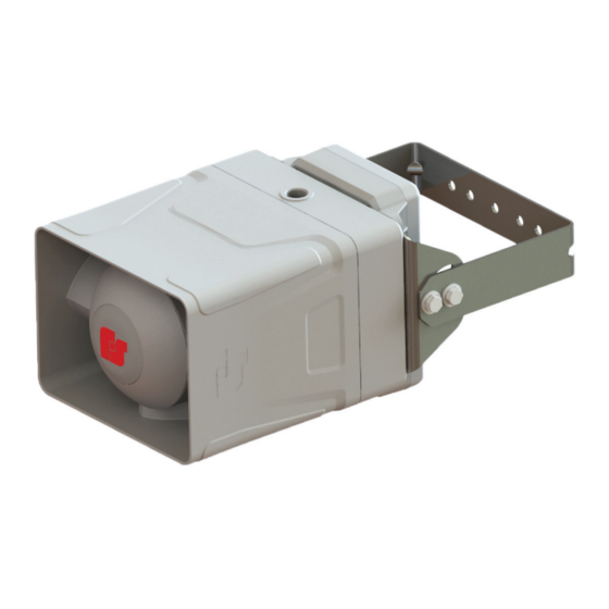
- Page 1 UltraVoice Compact Siren/Speaker ® Models: RF100U and RF100H Description, Specifications, Configuration, and Installation Manual 25500692 Rev. A0 1021 Printed in U.S.A. © Copyright 2021 Federal Signal Corporation...
- Page 2 A copy of this limited warranty can also be obtained by written request to Federal Signal Corporation, 2645 Federal Signal Drive, University Park, IL 60484, email to info@fedsig.com or call +1 708-534-3400.
-
Page 3: Table Of Contents
Contents Safety Messages..............................6 Safety Messages to Installers ..........................6 General Description ..............................9 Introduction .................................9 Features ................................9 Commander Software System (SFCDWARE) ....................10 Digital Voice Wizard ............................10 Ordering Information ............................11 Specifications ................................12 Configuration .................................14 Connectors ................................14 Jumpers and Switches ............................15 Site Address Switch–Located on the control board (S1) ...................15 Visual Indicators ..............................16 Radio Interface ..............................16 Programming Functions ............................16... - Page 4 Wiring to the Alarm Initiation Input Connections ....................32 Site Addressing and Encryption Configuration ....................33 Closing the Housing ............................33 Installing the Antenna ............................33 Ordering Replacement Parts ..........................34 Getting Service ..............................35 Tables Table 1 Ordering Information ..........................11 Table 2 Omni Antenna Kits ........................... 11 Table 3 YAGI Antenna Kits ............................12 Table 4 Specifications ............................12 Table 5 Environmental and Physical ........................12...
- Page 5 Figures Figure 1 Setting the Switch Number Example ....................15 Figure 2 Bracket attached to speaker........................19 Figure 3 Depth and height with bracket ......................20 Figure 4 Back view of speaker ..........................20 Figure 5 Bracket Kit I-IP100-PMW ........................21 Figure 6 Large Pole Mount with Yagi Antenna ....................22 Figure 7 Large Pole Mount with UHF Antenna ....................22 Figure 8 Large Pole Mount with VHF Antenna ....................23 Figure 9 Bracket Kit I-IP100-PM ...........................24...
-
Page 6: Safety Messages
Safety Messages Safety Messages It is important to follow all instructions shipped with this product. This device is to be installed by trained personnel who are thoroughly familiar with the country’s electric codes and will follow these guidelines as well as local codes and ordinances, including any state or local noise-control ordinances. - Page 7 Safety Messages • Read and understand all instructions before installing, operating, or servicing this equipment. • This product shall be mounted at a minimum hearing distance of ten feet per FEMA guidelines limiting sound level exposure to 123 dBc maximum sound level. •...
- Page 8 Safety Messages • To reduce the risk of electric shock, do not perform any servicing other than what is contained in the operating instructions unless you are qualified to do so. Refer all servicing to qualified service personnel. Always test the RF100 before using it after repairs have been made.
-
Page 9: General Description
General Description General Description Introduction The UltraVoice ® Compact Siren/Speaker (model RF100) is an outdoor or indoor RF-enabled high-powered speaker with an integral controller and radio. The RF100 is part of Federal Signal’s UltraVoice series of products. Use the RF100 as a warning and alerting device with both audible and visual indicators. -
Page 10: Commander Software System (Sfcdware)
General Description • Broadcasts live voice and prerecorded voice or tone files • Deliver intelligible voice messages from locally stored prerecorded files or from over- the-air P.A. • Includes a removable microSD card for custom message generation. Store over 4000 voice or tone messages that total up to 17 hours of recording time. -
Page 11: Ordering Information
General Description Ordering Information Table 1 Ordering Information Part Numbers Description RF100U Radio Controlled Siren/Speaker with UHF radio RF100H Radio Controlled Siren/Speaker with VHF radio RF100UX Radio Controlled Siren/Speaker with UHF radio for Hazardous Location RF100HX Radio Controlled Siren/Speaker with VHF radio for Hazardous Location Q19902536A Radio Programming Software with USB Interface Cable Kit... -
Page 12: Specifications
Specifications Table 3 YAGI Antenna Kits Part Number Part Number Frequency (with 35 ft cable) (with 10 ft cable) YAGI 1 YAGI 1-10 136-150 MHz YAGI 2 YAGI 2-10 150-174 MHz YAGI 10 YAGI 10-10 450-470 MHz Configuring the RF100 requires Federal Signal Commander ® application software (sold separately). -
Page 13: Table 7 Input And Outputs
Specifications Single Tone (Not a secure communications method) Frequency range 282-2600 Hz Tone timing 0.5-8 seconds maximum Tone Accuracy +/- 1.5% Tone Spacing 5.0% preferred, 3% minimum DTMF (Not a secure communication method) String length 3-12 standard DTMF characters Mark/Space timing: Decoder Minimum 50 ms/50 ms (See JP4 for fast DTMF) Decoder Maximum... -
Page 14: Configuration
Configuration Configuration Connectors The following table provides a description of the RF100 Controller Board connections. Table 8 Connectors AC Solid-State Relay Outputs 1 – Solid-State Relay #1 Hot 2 – Solid-State Relay #1 Neutral 3 – Solid-State Relay #2 Hot 4 –... -
Page 15: Jumpers And Switches
Configuration Jumpers and Switches The following table provides a description of the RF100 Controller Board jumpers and switches. Table 9 Configuration Jumpers (Located on the control board.) Disable Digital Receive. Short to disable. Short pins 1 and 2 for stand-alone mode Fast DTMF Decode. -
Page 16: Visual Indicators
Configuration Switch number Binary number Example: Switch numbers 1, 2, and 3 are binary numbers 1, 2, and 4. Add 1 + 2 + 4 = 7; 7 is the unit address NOTE: Programming details are in the software manual. The site address is stored at power up of the controller. -
Page 17: Installation
Installation Installation Read and adhere to all safety warnings in this manual before installing the RF100. SOUND HAZARD: The sound output of speakers is capable of causing permanent hearing damage. Ensure people are not exposed to sounds exceeding 120 dB– post warnings where applicable. -
Page 18: Determine The Mounting Method
Installation Determine the Mounting Method The following speaker and antenna mounting options are available for the RF100. Table 11 Speaker and Antenna Mounting Options Mounting Options Description Flat Wall Mount • A wall-mount bracket is included with the speaker. • The model AMB-W antenna wall mount bracket is available to provide a pipe mount off the surface of the wall. -
Page 19: Attaching The Mounting Brackets To The Speaker Housing
Installation Attaching the Mounting Brackets to the Speaker Housing The RF100 comes standard with a bracket attached for vertical wall or pole mount with optional pole accessories. To attach the bracket to the speaker: The mounting brackets are attached to the speaker, as shown below, using the six supplied 1/4-20 by 5/8-inch screws. -
Page 20: Figure 3 Depth And Height With Bracket
Installation Figure 3 Depth and height with bracket 0.18 6.68 5.88 2.53 10.09 2.00 12.87 Figure 4 Back view of speaker 9.97 5.22 0.16 8.10 0.74 UltraVoice Compact Siren/Speaker (Models RF100U and RF100H) ® Federal Signal www.fedsig.com... -
Page 21: Pole Mounting
Installation Pole Mounting The RF100 comes standard with a bracket for vertical wall or pole mount with optional pole accessories. Large Pole Mounting (6-inch diameter or larger) Use the I-IP100-PMW bracket kit for poles that have a diameter of 6 inches or larger. The following figures illustrate typical examples of a pole installation with a bracket and antenna. -
Page 22: Figure 6 Large Pole Mount With Yagi Antenna
Installation Figure 6 Large Pole Mount with Yagi Antenna Utility pole AMB-LP-Y Yagi antenna Bolt for ground wire NOTE: Bands are not included with the kit. Figure 7 Large Pole Mount with UHF Antenna UHF Antenna AMB-LP-U Utility pole Bolt for ground wire NOTE: Bands are not included with the kit. -
Page 23: Small Pole Mounting (2-3/8 Inch To 4-1/2 Inch Diameter Poles)
Installation Figure 8 Large Pole Mount with VHF Antenna VHF Antenna Utility pole AMB-LP-H Bolt for ground wire NOTE: Bands are not included with the kit. Small Pole Mounting (2-3/8 inch to 4-1/2 inch diameter poles) Use the I-IP100-PM bracket kit for poles that have a diameter between 2-3/8 and 4-1/2 inches. -
Page 24: Figure 9 Bracket Kit I-Ip100-Pm
Installation Figure 9 Bracket Kit I-IP100-PM Figure 10 Small Pole Mount with Yagi Antenna Utility pole AMB-SP-Y Yagi antenna Bolt for ground wire UltraVoice Compact Siren/Speaker (Models RF100U and RF100H) ® Federal Signal www.fedsig.com... -
Page 25: Figure 11 Small Pole Mount With Uhf Antenna
Installation Figure 11 Small Pole Mount with UHF Antenna UHF Antenna AMB-SP-U Bolt for ground wire Utility pole Figure 12 Small Pole Mount with VHF Antenna VHF Antenna Utility pole AMB-SP-H Bolt for ground wire Description, Specifications, Configuration, and Installation Manual Federal Signal www.fedsig.com... -
Page 26: Mounting With Omni Direction Bracket (2-3/8 Inch Diameter Pole)
Installation Mounting with Omni Direction Bracket (2-3/8 inch diameter pole) Use the I-IP100-OMNI bracket kit to create an omni-directional speaker. The speaker is mounted as described in the Small Pole Mounting section, with the omni bracket mounted at a distance of 2.0 inches from the speaker. To mount the speaker with the optional I-IP100-OMNI bracket Identify the desired location for the bracket. -
Page 27: Using Optional Warning Lights
Installation Using Optional Warning Lights Warning lights, such as strobes, often have a high inrush current that may damage mechanical relays. A solid-state relay is used to minimize potentially high inrush current devices. Use the AC solid-state relay outputs for control of the AC-powered visual indicators or other devices. -
Page 28: Figure 14 Fb2Pst Strobe With Rf100
Installation Figure 14 FB2PST Strobe with RF100 Pipe Nipple 1/2" NPT 3" overall length (Recommended, supplied by others) Side View Front View For an FB2PST Strobe, the following is recommended (supplied by others): 1/2-inch NPT Pipe Nipple (3 inches overall length). Figure 15 151XST Strobe with RF100 3/4"... -
Page 29: Opening The Housing
Installation Figure 16 225XST/225XL Strobe with RF100 Pipe Nipple 1/2" NPT 3" overall length (Recommended, supplied by others) Side View Front View For a 225XST/225XL Strobe, the following is recommended (supplied by others): 1/2-inch NPT Pipe Nipple (3 inches overall length). Opening the Housing Tools required: •... -
Page 30: Digital Voice Recording
Installation Digital Voice Recording The RF100 control board includes a microSD card capable of storing over 4,000 voice or tone messages that total up to 17 hours of total recording time. Federal Signal can provide custom or standard voice messages. The RF100 comes from the factory with a standard set of voice and tone files loaded on the microSD card. -
Page 31: Wiring Power To The Control Board
Installation Wiring Power to the Control Board JP6 and JP7 are connected in parallel. Federal Signal recommends using JP6 as the AC input to allow room for wires coming in from the 3/4-inch NPT opening. When power is supplied to JP6, it is connected through the PCB to JP7 and the four AC solid-state relay outputs on JP1. -
Page 32: Wiring To The Solid-State Relay Outputs
Installation Wiring to the Solid-State Relay Outputs DO NOT EXCEED THE VOLTAGE AND CURRENT RATINGS: Do not exceed the voltage and current ratings listed in the Specifications section of this manual. Damage to the controller board may occur. AC Solid-State Relay Outputs (JP1) The solid-state relay outputs are designed to drive AC devices such as strobes or LED visual indicators. -
Page 33: Site Addressing And Encryption Configuration
Installation Site Addressing and Encryption Configuration The following tasks are performed while the cover is open: • Setting the Site Address Switch (S1) (See “Site Address Switch–Located on the control board (S1)” on page 15.) • Configuring the Security Code and Encryption Key (Optional): If you are using encryption and security codes, they can be installed during installation or setup. -
Page 34: Ordering Replacement Parts
Installation Ordering Replacement Parts To order replacement parts, call Customer Support. See Getting Service. Table 14 Replacement Parts Description Part Number Service Kit, 20000478 PCBA Q2000478B Includes: Control PCB Only Q19902408A-01 VHF Ritron ® Radio Q19902408A-02 UHF Ritron ® Radio Radio Programming Software and Interface Cable Kit Q19902536A RF100 Lightning Surge Suppressor... -
Page 35: Getting Service
Getting Service Getting Service If you are experiencing any difficulties, contact Federal Signal Customer Support at 800-548-7229 or 708-534-3400 extension 7511 or Technical Support at 800-524-3021 or 708-534-3400 extension 7329 or through e-mail at techsupport@fedsig.com. For instruction manuals and information on related products, visit http://www.fedsig.com/. Description, Specifications, Configuration, and Installation Manual Federal Signal www.fedsig.com... - Page 36 2645 Federal Signal Drive University Park, Illinois 60484-3167 www.fedsig.com Customer Support 800-548-7229 • +1 708 534-3400 Technical Support 800-524-3021 • +1 708 534-3400...
Need help?
Do you have a question about the UltraVoice RF100U and is the answer not in the manual?
Questions and answers