
Subscribe to Our Youtube Channel
Related Manuals for Megger PAT400 Series


Summary of Contents for Megger PAT400 Series
- Page 1 PAT400 Series Portable Appliance Testers User Manual GlobalTestSupply www. .com Find Quality Products Online at: sales@GlobalTestSupply.com...
- Page 2 For your own safety and to get the maximum benefit from your instrument, please ensure that you read and understand the safety warnings and instructions before attempting to use the instrument. These instruments are designed and manufactured by: Megger Instruments Limited reserves the right to change the specification of these instruments at any time without prior notice. GlobalTestSupply www.
-
Page 3: Table Of Contents
CONTENTS Unpacking the carton..........................5 Safety Warnings ............................5 Symbols used on the instrument......................6 Instrument Layout............................8 Overview of the PAT400 ......................... 8 Instrument layout ............................ 9 Button functions............................ 10 HOT KEY descriptions .......................... 10 Display information..........................11 Screen navigation ..........................11 Text fields (free form box) and Drop down boxes................ - Page 4 10.8 ABOUT - PAT400 software version and Megger contact details ............70 PAT400 enhancements: Firmware release V2.40 ................... 71 11.1 User names, account status and Login ....................71 11.2 Power Up and Log in/Log out options ....................72 11.3 Managing accounts..........................74 11.4...
-
Page 5: Unpacking The Carton
Unpack the carton contents carefully. There are important documents that you should read and keep for future reference. Please complete the pre-paid warranty card and return it to Megger Instruments Limited as soon as possible to help us reduce any delays in supporting you should the need assistance. -
Page 6: Symbols Used On The Instrument
Serviceable fuses should only be replaced with those that are suitably rated In case of an emergency use an easily accessible power point Only use Megger approved accessories with this product CAT II Measurement category II: Equipment connected between the electrical outlets and the user’s equipment. -
Page 7: Instrument Layout
Instrument Layout Overview of the PAT400 The PAT400 series of portable appliance testers are fully automated testers for the fast safety testing of portable electrical equipment. The PAT400s will operate from 230 Vac or, for UK variants 230Vac and 110 Vac supplies. -
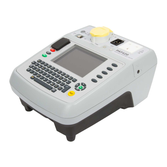
Page 8: Instrument Layout
Instrument layout IEC/Extension lead 110 V test socket (UK Only) Mains test socket return test socket Flash test socket Fuse checker Bond/continuity HOT KEYS socket Lead null post QVGA Colour display USB interfaces Up/Down/Left/Right navigation keys Power OFF OK button Home button TEST button Escape button... -
Page 9: Button Functions
Button functions Button functions Power down – Prevents battery discharge Hot keys. Returns to HOME screen Function depends on adjacent display icon. Used for fast selection of options Escape – Exit screen without saving HOT KEY descriptions Home screen SETUP screen Class 1 test groups Test group manager Class II test groups... -
Page 10: Display Information
Display information Menu bar – Provides navigation path and menu options. See NOTE below Main display area Display and test Hot keys result information Quick access to frequently used test Additional menu groups, and other options options. NOTE: Users tab is only available on Firmware version V2.4 and above. Screen navigation Use the UP/DOWN and LEFT/RIGHT arrows to navigate around the menu and asset screens. -
Page 11: Battery And Fuse Location, Fitting And Replacement
Free form box. Text or numbers can be entered as required. Text can be entered from a keyboard or barcode scanner. In some instances a “free form” box can become a “drop down” box, such as the asset ID field. In this case it will appear with the drop down icon as below: 2) Drop down boxes: Drop down boxes already contain a list of items. - Page 12 re-started within 5 minutes. The battery shall only be replaced by an equivalent rechargeable battery when the re-boot facility ceases to work. To replace the rechargeable battery: Switch off the instrument. Disconnect the instrument from any electrical circuits. Remove the battery cover. Remove the old battery and refit new battery following correct polarity (as marked on the battery compartment) Replace the battery cover.
- Page 13 Remove the fuse cover on the underside of the PAT tester. Remove each fuse in turn and check for failure. Replace as necessary. If no fuses have failed, contact Megger Technical services group on 44 (0) 1304 502 102. Replace fuse cover when complete. Note: symbol on the batteries is a reminder not to dispose of them with general waste at the end of their life.
-
Page 14: Getting Started
Getting started Switching ON the PAT400 1) Connect the instrument to a suitable electrical supply, either 230 Vac (or 110 Vac for UK instruments). For testing 230 V electrical equipment, connect the PAT tester to a 230 V electrical outlet. For testing 110 V electrical equipment, connect the PAT tester to a 110 V electrical outlet, using the optional 110 V to 230 V supply lead adaptor. - Page 15 Using the RIGHT/LEFT and OK keys to enter the date and time Date format is DD / MM / YYYY Time format is 24 Hr Hr / Min / Sec Press the SAVE HOTKEY to accept changes. Further changes can be made in the menu SETUP options section 10.5 On completion of the initialisation the following warning screen is displayed when the PAT tester is switched on.
-
Page 16: Home Screen Explained
HOME screen explained The HOME screen is the start point of all testing. Menu functions: Class I test groups Home Test launch screen HOT KEY access Class II test groups Instrument status Setup Class IEC (Power) and Client extension lead test groups Location Company Plug-In RCD test groups... -
Page 17: Testing With A Pat400
Testing with a PAT400 Connecting an asset to the PAT400 Assets are tested through the test connectors on the top of the instrument. An asset is simply plugged into the appropriate socket. A power cord (IEC lead), or an extension lead needs to be “wrapped back” to the small IEC socket on the top of the instrument. -
Page 18: Testing An Asset
on the PAT400. 3.1.3 Connecting an extension lead To connect an extension lead to the PAT400: 1) Connect the mains plug to the mains test socket on the PAT400 2) Using the extension lead adaptor, connect the furthest socket on the extension lead to the IEC socket on the PAT400. To connect a 110 V power lead, use the 110 V to IEC plug adaptor (optional accessory). - Page 19 Option 1: Starting a TEST – USING HOT KEYS Select a Class I, Class II, IEC/extension lead or RCD test group by pressing one of the HOT KEY options: A list of TEST GROUPS are displayed that are relevant to that type of equipment Example: Class I test groups Class I test groups Class II test groups...
- Page 20 If the asset is already in the database the details of the asset will be displayed as below: Press the TEST button and the test sequence will commence. Go to 3.3 TESTING PROGRESS. Alternatively to search through the asset database, press the FIND ASSET Hotkey.
- Page 21 Copy last asset added from list Copy last asset added and increments Asset ID to next available number. * Indicates mandatory fields that are required to save the asset data. Further information on the COPY LAST ASSET Hotkey and COPY & INCREMENT ASSET Hotkeys can be found in section 5.
- Page 22 On completion of a test, only Asset IDs and Test groups have to be added before the test is completed. All other data is optional. NOTE: If NO Asset ID is entered, press the Test Group Hotkey and type in the test group.
-
Page 23: Test Progress
Additional information can also be added, but this is not essential. NOTE: When scanning an Asset ID that exists in the database under a location that is different to that set in the PATs current status, a yellow warning indicator will show on the Location field as below. -
Page 24: Remote Probe And Clip
Test results screen Test results column List of tests in test group Test limits column Green – Test passed Amber – Test in progress Pass limit set for this test Grey – Test pending Actual measurement result Current test values or Instructions during the test sequence Interruption to automatic testing... - Page 25 The insulation test probe is connected to all exposed metal parts to ensure electrical separation from earth. 3.4.1 Test lead resistance null The resistance of the Bond lead can be “nulled” to remove the lead resistance from the measured resistance. This is important when testing very low resistances where the test limit is set to 0.1ohms. Also, the resistance of an extension lead (IEC or Power cord) can be nulled, if the lead is longer than the Red test lead supplied with the PAT.
- Page 26 Press the TEST button. The PAT400 will display the value of the test lead as a Null SET value, and display the symbol in the top of the screen as below: displayed inside means an extension lead null is also set. To remove the Bond Lead Null select the “Remove Lead Null”...
-
Page 27: Short Circuit Assets
Press the NULL Hotkey. The Lead Null screen will appear with the Set Lead Null option highlighted: (If an extension lead null value is already set the lead null symbol will be displayed) Connect the extension lead adaptor between the Mains test socket and the IEC socket on the front panel as below: Scroll down to select “Set Extension Lead Null”... -
Page 28: Aborting A Test
Repair codes – Allows repair details to be added to asset test results – See section 3.10 below. Save the test results to memory and print a barcode label (a Megger USB barcode printer must be connected prior to requesting this function). -
Page 29: Visual Failure
Repeat test sequence Repair code Print bar code label & SAVE results to memory SAVE results to memory Example: Asset has failed the insulation test. Pass limit set to 1.0 MΩ, Measurement recorded at < 0.1 MΩ. The same options are available as an asset that has passed. See Section 3.7 for completion of testing. Visual failure If the current test group contains a visual test sequence then the visual test popup will appear. -
Page 30: 3.10 Repair Code
Three types of information can be entered: a) Notes - To describe the type of failure. b) Check boxes - Quick entry for standard failure types. c) Repair code - See Section 3.10 below Press the TEST key to complete the test process. The display will now show the TEST FAILED screen. -
Page 31: 3.11 Cable Compensation
On completion of the repair code screen press the TEST key to log the changes, then press the SAVE or SAVE and PRINT Hotkeys to store the results. 3.11 Cable compensation A power cord, appliance lead or extension lead will frequently exceed the nominal length and consequently the resistance limit set in the standard test groups. -
Page 32: 3.12 Warnings
Press Esc to fail the Asset and save or abort the results, Press “R” to re-run the continuity test. Enter the cable Length in metres and the conductor Cross-Section (mm ) OR a Resistance can be entered if this is known. Press TEST to complete the test. - Page 33 The PAT400 will test for a good supply earth during initialisation. A faulty or missing earth will return the error: Error 73 – Mains supply Earth Fault 3.12.4 Parallel earth paths If the PAT400 detects more than one earth path, the warning: Unable to verify earth connection, Parallel paths may exist.
-
Page 34: Using The Memory
Using the memory Important overview All records are stored under a “client”. The PAT400 can store up to 100 (50 on firmware releases prior to 2.20) clients. Each client can have up to 2 000 (50 on firmware releases prior to 2.20) Locations. There is a maximum of 25 000 total locations per database. -
Page 35: Saving A Test Result
Definitions of fields Field Limit Description Asset ID:* 10 000 Unique number or combined letters and numbers. Enter by typing from the keyboard or scanning a barcode. Separate clients can use the same ID. But one Client cannot have two identical Asset IDs. Test Group:* Drop down box of available test groups. - Page 36 Enter the Asset ID. This can be via the keyboard or scanned in by barcode scanner. If an Asset ID already exists in memory, a “duplicate Asset ID” warning will be displayed. In this case, enter a different Asset ID number. Examples of Asset ID formats: (Asset IDs are limited to 20 characters) 0001, 0002, 0179, 7082 MEGGER0001, MEGGER0002...
-
Page 37: Adding Assets To Memory
Adding assets to memory Assets can be saved to memory after they are tested, as above, or before any testing starts. Copying a previously added asset using the COPY ASSET Hotkey or COPY ASSET AND INCREMENT ASSET ID Hotkey in Section 5.2. Alternatively: Asset data can be loaded from PowerSuite via a USB stick, Section 7.2. -
Page 38: Copying The Previously Added Asset
Copying the previously added asset From the HOME screen, press the ADD ASSET Hotkey. The following empty asset screen will appear: To recall the last asset to the screen press the COPY ASSET Hotkey. This will recall the last asset added to the database of the current Client. The Asset ID can then be edited as required. Change the Asset ID. - Page 39 Change any other asset information as necessary. Press the SAVE Hotkey to save the ASSET to memory. GlobalTestSupply www. .com Find Quality Products Online at: sales@GlobalTestSupply.com...
-
Page 40: Editing And Deleting Assets And Results
Editing and deleting assets and results All asset data can be edited or deleted as required. For deletion of Test Groups see section 8. For deletion of Client and Locations see section 10. Editing asset data From the HOME screen, enter the SETUP menu option by pressing the RIGHT arrow key. EDIT asset Press the EDIT ASSET Hotkey. -
Page 41: Deleting Assets
closest match as you type. Note: The first 2 000 Asset IDs are loaded into the drop down list. To access the next 2 000 assets, press and hold the RIGHT ARROW to scroll down to the bottom of the first 2 000 assets. Select ‘Next…’... -
Page 42: Data - Test Results And Data Transfer
DATA – Test results and data transfer Data storage – backup and restore The PAT400 can store up to 10 000 electrical assets with associated test records. Megger STRONGLY RECOMMEND this data is backed up frequently. MEGGER CANNOT ACCEPT RESPONSIBILITY OR ANY LOST DATA HOWEVER CAUSED. -
Page 43: Importing / Restoring Data From Usb Memory Stick
Press OK to initiate backup. If the file name clears without backup starting, the file name contains excluded characters. Only 0 to 9 and A to Z should be used. On completion the display will show the message “Backup complete”. There are no limits to the number of times you can backup a database. - Page 44 WARNING: Importing or restoring a file will overwrite the existing assets, results, test groups, clients and locations in the database. Press OK to continue. The PAT400 will search for any database files in the root directory. A drop down box appears. Press the OK key and then the DOWN arrow to scroll through the list, or use the RIGHT arrow key to page through the list.
-
Page 45: Export Results To Csv
Press OK to accept the file for import/restore. The file will be imported. On completion a message will be displayed and the buzzer will sound. DO NOT SWITCH OFF THE PAT400 DURING THE USB OPERATION! WARNING: Importing or restoring a file will overwrite the existing assets, results, test groups, clients and locations in the database. -
Page 46: Accessing Test Results
Select Export Results to USB and press OK. The following screen will appear. Enter a name for the CSV file. Up to 8 characters can be used. Use letters and/or numbers. Press OK when ready. The CSV file will be saved to the USB memory stick. On completion the following message will be displayed and the buzzer will sound. - Page 47 The ‘View Test Results’ screen will be displayed as below: FIND asset ADD asset EDIT asset Enter the Asset ID or press the FIND ASSET Hotkey. If there are a large number of Assets IDs, this may take a few seconds. When the desired Asset ID has been found, Press OK to accept.
- Page 48 Press the VIEW TEST RESULTS Hotkey. The Test Results screen will be displayed for that asset as below. To exit this screen press HOME or Esc. Note: Barcodes can be printed by using the PRINT BARCODE Hotkey 7.4.2 Printing barcode labels Duplicate barcode labels can be printed from the VIEW TEST RESULTS page.
-
Page 49: Test Groups
Test groups Overview of test groups Test groups are used to simplify the testing of an asset. A test group is a collection of tests that when run, perform all the tests allocated to that test group. The PAT400’s are shipped with a range of test groups for the majority of electrical equipment that will require testing, as detailed below. - Page 50 Note: If the number of test groups reaches 100, the ADD Hotkey will change to a Icon. Complete the fields as required. An example of a typical standard Class I test may look like: Next page Definitions to fields: NAME Test group name - This can be up to 10 characters - For compatibility with PAT4 see section 11...
-
Page 51: Allocating Test Groups To Hotkeys
Options Class 1 - Class 2 - EXT FLASH Check box – configuration options available on second page LEAKAGE Check box – configuration options available on second page LOAD Check box – configuration options available on second page Check box – configuration options available on second page These fields require mandatory data. - Page 52 Class I Class II Power cord / Extension lead Add Asset Using the DOWN ARROW, navigate to the desired row (1 – 9) as below: Press OK to access the drop down list of available test groups. Select the required TEST GROUP and press OK. The TEST GROUP will be allocated to the selected field.
-
Page 53: Editing A Test Group
NOTE: The TEST GROUPS can be freely allocated to any of the nine fields and in any of the four Hotkeys. If desired a CLASS I TEST GROUP can be allocated to the RCD Hotkey for example. Editing a test group Each test group can be edited or deleted NOTE: When restoring a database the test groups will also be overwritten. -
Page 54: Deleting A Test Group
Select the test group to be edited and press OK to accept. The test group settings can be adjusted and saved as per the test group ADD function above. WARNING: Changing a Test Group will affect all assets that use that test group. Deleting a test group To delete a test group: From the HOME screen use the RIGHT ARROW key to select the SETUP tab. -
Page 55: Repeated Tests
Note: A test group cannot be deleted whilst there are assets in the database that are using that test group. Repeated Tests It is possible to create test groups with repeated Bond, Continuity, Insulation and Flash tests. An example screen is shown below. Repeated tests are setup by choosing an option in the Cycles column. -
Page 56: Quick Test - Qt
Quick test - QT The Quick Test (QT) key provides instant access to continuity, bond, insulation, leakage, RCD, load (Operational) and flash testing, without having to create a test group. NOTE: Some tests shown below may not be available, depending on the instrument being used. - Page 57 Follow on-screen instruction as necessary. On completion of the test the final measurement will be displayed. Quick test times can be changed in SETUP. Refer to section 10.4 GlobalTestSupply www. .com Find Quality Products Online at: sales@GlobalTestSupply.com...
-
Page 58: Setup Menu Options
SETUP menu options The SETUP menu options allow changes to the instrument configuration that cannot be accessed by Hotkeys. 10.1 Clients The PAT400s are shipped with the CLIENT and LOCATION set to DEFAULT. This can be changed, or additional Clients and locations can be added, edited or deleted. The DEFAULT CLIENT and LOCATION can only be deleted after other additional CLIENTS AND LOCATIONS are added. - Page 59 On completion, press the SAVE Hotkey. The display automatically jumps to the ADD LOCATION screen. Add the location details. Only Location name is mandatory. On completion, press the SAVE Hotkey. A new CLIENT and LOCATION has been added to the database. The current CLIENT and LOCATION has been updated to the new CLIENT and LOCATION automatically.
- Page 60 Press the DELETE hotkey. A popup message will ask you to confirm. 10.1.3 Changing Clients To change between different Clients in the PAT400: From the SETUP tab press the SELECT CLIENT Hotkey. Press the OK key to open the drop down list. Select the desired Client and press OK. Press the SAVE Hotkey to store the change.
-
Page 61: Locations
10.2 Locations Multiple locations can be added to one CLIENT, up to a maximum of 2 000*. To add a LOCATION, select the LOCATION option from the SETUP menu. Follow the same process as adding Clients in Section 10.1. * Firmware revisions earlier than 2.2 were limited to 50 locations per Client. 10.2.1 Adding Locations Select LOCATION from the SETUP menu and press OK. - Page 62 Select LOCATION from the SETUP menu and press OK. In the Location screen select the EDIT Hotkey. Select the desired Location then press the NEXT PAGE Hotkey. Change the Location details as required. It is not possible to change the associated Client. After the details have been changed press the SAVE hotkey.
- Page 63 Select the desired Location then press the NEXT PAGE Hotkey. Press the DELETE Hotkey. A popup message will ask you to confirm. 10.2.3 Changing Locations You may only change to a Location in the current client. In the SETUP tab press the SELECT LOCATION Hotkey.
-
Page 64: Company
Press the SAVE Hotkey to store the changes. 10.3 Company The Company page provides data entry for the testing company to add their company details to the PAT400. The “Label Text” is a field that is used to add text to printed labels. For example you may wish to add the testers name to a label. -
Page 65: Date / Time Settings
Insulation test Bond test Load (Operational) test Leakage test To adjust the QUICK TEST time settings: Select QUICK TEST KEYS from the SETUP menu options. Press OK to display the Quick Test Config screen. Navigate to the desired field to adjust the test time. Press ESC to save and exit. -
Page 66: Changing Language
Press OK to accept. For DATE settings, use LEFT/RIGHT arrow keys to select the field to be changed. Enter the desired values using the keyboard. For TIME settings, use the DOWN arrow key to select TIME, then the LEFT/RIGHT arrow keys to select the fields to be changed. -
Page 67: Restoring Default Settings
WARNING: Restoring factory default settings will overwrite all stored data and settings. Stored data will be lost. Megger strongly recommend backing up all data prior to restoring factory settings. Backups can be restored if necessary. To restore the PAT400 to the factory shipped configuration... - Page 68 Existing records and test groups should be backed up prior to restoring factory settings. Press OK to access the Restore Defaults screen. Press OK to proceed, or Esc to abort. A popup message will ask you to press Y to confirm restore to defaults. The PAT400 will then reboot with the default settings.
-
Page 69: About - Pat400 Software Version And Megger Contact Details
10.8 ABOUT - PAT400 software version and Megger contact details To select the product information and Megger contact details: Using the RIGHT ARROW key, select SETUP in the top menu option, then the DOWN arrow to select ABOUT option. Press OK to access the ABOUT screen. -
Page 70: Pat400 Enhancements: Firmware Release V2.40
PAT400 enhancements: Firmware release V2.40 The PAT400 now includes the following additional features: Multiple operator accounts • Login (PIN) facilities • Security levels (Supervisor/User accounts) • Experience levels (Expert mode) • Reverse polarity earth leakage testing • The additional functionality is located under the new “Users tab” in the menu options as below: 11.1 User names, account status and Login The PAT400 supports single or multiple operators. -
Page 71: 11.2 Power Up And Log In/Log Out Options
Username: This can be changed as required Additional users can be added Maximum field length - 30 User status: Indicates the level of control and configuration available to the operator 11.2 Power Up and Log in/Log out options Factory default Power-up When powering up the PAT400 for the first time there is no need to log in. - Page 72 The PAT400 will display the warnings screen. If the wrong PIN is entered, the display will show the warning: “Incorrect PIN entered” Retry with the correct PIN. Successful log in will then display the “Warnings” screen. Press OK to indicate you have read and understood the warnings.
-
Page 73: 11.3 Managing Accounts
Use the UP/DOWN arrows to select the required User name and press OK. Enter the PIN for the new “Username” and Press the Hotkey. Logging Out & Power down Unless the operator has logged OUT of their account on Power-down, the operator will remain logged IN to the PAT400 on Power-up. - Page 74 Supervisor status – Supervisor box checked An account with “Supervisor” status has unlimited access to all functionality and configuration of the PAT400. Any account with “Supervisor” status can create additional accounts and control the status of other accounts, including deleting other accounts. User status –...
- Page 75 Press the SAVE Hotkey to save the change. If the Feature is disabled, the Expert mode check box will be grayed out. Reverse L-N Polarity (Only available in some models) Refer to section 12 Reverse L-N Polarity. 11.3.2 Changing the default Supervisor account The factory set user account name is called “default”.
- Page 76 Usernames must be between 3 and 30 characters, A-Z and 0-9 (upper or lower case). When completed press OK. To add a PIN, follow section 11.3.3 To add a PIN to an account step (3), If no PIN is to be entered, press the SAVE Hotkey to save the change.
- Page 77 Press the Edit Hotkey Use the DOWN arrow to select the PIN field. Enter a PIN number from 0000 to 9999. Only use numbers from 0 to 9. Press the DOWN arrow to select the “Confirm PIN” field. Enter the same PIN number. Press the SAVE Hotkey to store the changes.
- Page 78 Press the Edit Hotkey. Use the DOWN arrow to select the PIN field. Enter a new PIN number. Press the DOWN arrow to select the “Confirm PIN” field. Enter the same (new) PIN number. Press the SAVE Hotkey to store the changes. If the account has “User”...
- Page 79 Enter a new PIN and press the DOWN arrow to the Confirm PIN field. Enter the Same PIN. Press the SAVE Hotkey to store the changes. To remove a PIN from an account: If you account has “Supervisor” status: Use the same method as to change a PIN, but delete the PIN number entirely. Repeat for the Confirm PIN field.
- Page 80 Using the arrow keys, navigate to “Manage Users” option in the USERS Tab and Press OK. Note: An additional Delete hotkey may be present if there is already more than one account. Press the ADD Hotkey to bring up the Add User screen. GlobalTestSupply www.
- Page 81 Enter a user name. Names must be between 3 and 30 characters, A-Z and 0-9 (upper or lower case). Press the DOWN arrow. Enter a PIN if required. The PIN must be 4 digits using only numbers 0-9. Press the DOWN arrow. Enter the same PIN in the Confirm PIN field. Press the DOWN arrow to Expert Options.
-
Page 82: 11.4 Recovery Login
If this is the account to be deleted, press the Delete Hotkey. Press the OK key to display a list of accounts and use the DOWN/UP arrow keys to highlight the require account and press OK. Press the Delete Hotkey to delete the account. The Warning message will be displayed. - Page 83 Pressing OK will remove all users from the PAT400 and create a single Supervisor account. If necessary, contact your supervisor before continuing, or press ESC to abort. Press OK to continue. The display will show a standard warning screen. Press OK after reading and understanding the warnings given. The PAT400 is now logged into a standard Default user account as a “Supervisor”.
-
Page 84: Reverse L-N Polarity (Not Available On All Instruments)
12. Reverse L-N Polarity (not available on all instruments) In countries where the power plug can be reversed in the socket (example: Schuko) the earth leakage tests can be configured to test in normal “forward” polarity or “normal and reversed” polarity. Checking the “Reverse L-N Polarity”... - Page 85 Press the SAVE Hotkey to store the changes. Operators who have “Supervisor” status or “Expert” user status may also configure the Reverse L-N Polarity feature in the Expert Options screen. Use the UP or DOWN arrow key to highlight the Reverse L-N Polarity check box. Press the OK key to enable or disable the reverse L-N testing.
- Page 86 Press the SAVE Hotkey to store the changes. GlobalTestSupply www. .com Find Quality Products Online at: sales@GlobalTestSupply.com...
-
Page 87: Measure Pe Option (Not Available On All Instruments)
13. Measure PE Option (not available on all instruments) Some PAT testing practices allows the Protective Earth bond testing to be skipped if it is deem impossible to access an exposed PE contact area. For PAT testers configured to allow for such situation there is a “Measure PE Option”... - Page 88 GlobalTestSupply www. .com Find Quality Products Online at: sales@GlobalTestSupply.com...
-
Page 89: Pat4 Compatibility
Client 2 Asset 0001, 0002, 0003 However the same Asset ID cannot be used in different locations under one client. To transfer data from the PAT4 to the PAT400, the transfer must be made using Megger PowerSuite Professional. GlobalTestSupply www. -
Page 90: Care And Maintenance
Care and maintenance The PAT400 should only be opened or repaired by an approved Megger service centre or by Megger Instruments Limited. To clean the instrument; disconnect the instrument from the power supply then use a clean cloth dampened with water or isopropyl alcohol. -
Page 91: Carry Case
These are passed through the D-loops on the outside of the case and secured to the underside of the pouch using the Velcro fixings. An additional storage pouch is available from Megger Limited for extended storage, such that there is a pouch on both the inside and outside of the carry case. -
Page 92: Appendix A - Test Types Explained
Appendix A – Test types explained Each test group is constructed from a series of individual tests. The tests are selected depending on the electrical construction of the asset under test. The operator must understand the type of electrical construction of the asset before a correct selection of tests can be made. The tests available on the PAT400’s are as follows: Continuity &... -
Page 93: Insulation Testing
also fail due to increased resistance induced by long cable lengths. When a bond test fails the PAT400 will display a lead compensation table, allowing the pass limit to be modified. See section 3.11 and Appendix A.6 for further details on lead compensation. Insulation testing This is used to confirm there is separation between the live conductors (live and neutral) and any accessible conductive parts. -
Page 94: Load Testing
Also called absence of potential Test voltage: 230 Vac 50 Hz " 9.99 mA 110 Vac 50 Hz " 9.99 mA During this test the appliance under test is powered from its normal mains supply and the test lead and probe is connected to the PAT terminal. -
Page 95: Power Lead/Extension Lead Testing
Power lead/extension lead testing Power cords and extension leads are tested in a similar way. The principle differences are the need to use an extension lead adaptor when testing extension leads, as the lead must be looped back to the PAT400 to allow bond and polarity testing. - Page 96 the equipment touching other earthed equipment or from touching the ground. Parallel earth paths affect measurement accuracy and in worst case situations can lead to equipment being passed as safe when there is no proper earth connection through the electrical outlet. b.
-
Page 97: Pat400 Factory Default Test Groups
PAT400 Factory Default Test Groups Test Groups for UK PAT Variants: Test Test Pass Durati Group Class Description Test Applied Limit Vbnm,znm,.nz Visual Inspection Earth Bond at 10A Insulation test at 500V ≤0.1Ω Operation test (230V) ≥1MΩ Standard Class 1 Differential Earth ≤3000VA PAT420... - Page 98 Visual Inspection Visual Inspection Earth Continuity Insulation test at 500V ≥2MΩ PAT410 Insulation test at 500V ≤0.1Ω Desk Fan Operation test (230V) ≤200VA PAT420 Portable or hand- Operation test (230V) ≥1MΩ PAT410 Double Insulated Touch Current (230V) ≤0.25mA PAT450 held Class 1 Differential Earth ≤3000VA PAT420...
- Page 99 Test Groups for Australian/New Zealand PAT Variants: Test Test Group Class Description Test Applied Pass Limit Duration Used in Visual Inspection PAT410 Standard Class 1 Earth Continuity (200mA) ≤1Ω PAT420 AU-SC1 Earthed Equipment Insulation test at 500V ≥1MΩ PAT450 Visual Inspection Earth Continuity PAT410 Standard Class 1...
- Page 100 Test Groups for International/European PAT Variants: Test Test Group Class Description Test Applied Pass Limit Duration Used in Visual Inspection Insulation test at 500V Substitute Earth ≥2MΩ PAT410 PAT450 N-KL2STD Klasse 2 Leakage ≤0.5mA Klasse 2 Visual Inspection elektronisch Differential Earth PAT410 N-KL2ELEC regeling...
- Page 101 Standard Class Visual Inspection Earthed RCD 30mA test Equipment with Earth Continuity RCD Protection Operation test (230V) ≤0.1Ω PAT410 200mA Differential Earth ≤3000VA E-SC1B-RCD Continuity Test Leakage (230V) ≤3.5mA PAT450 Visual Inspection Typical Class 2 Insulation test at 500V ≥2MΩ Double Operation test (230V) ≤3000VA...
- Page 102 Portable RCD Visual Inspection PAT410 E-RCD 30mA RCD 30mA test PAT450 Portable RCD Visual Inspection PAT410 E-RCD FULL (5 tests) RCD full test sequence PAT450 Visual Inspection Earth Continuity Portable or Insulation test at 500V ≤0.1Ω hand-held Operation test (230V) ≥1MΩ...
-
Page 103: Appendix C - Specification
Appendix C - Specification SPECIFICATIONS Electrical supply range PAT-UK 230 V ±10% ±1 V @ 50 Hz ±1% ±0,1 Hz PAT-UK 110 V ±10% ±1 V @ 50 Hz ±1% ±0.1 Hz PAT-NL-ES 230 V ±10% ±1 V @ 50 Hz ±1% ±0,1 Hz PAT-DE 230 V ±10% ±1 V @ 50 Hz ±1% ±0,1 Hz PAT-CH... - Page 104 ±5% ±50 digits (100 VA - 999 VA) ±5% ±100 digits (1000 VA - 3700 VA) Resolution: 1 VA (0 to 3700 VA) Display range: 0 to 3990 VA Reading corrected to 230 Vac or 110 Vac Extension lead test Tests performed: Bond, insulation &...
-
Page 105: Appendix D - Ordering Information
Appendix D - Ordering information ORDERING INFORMATION Order Code Included accessories (relevant to territory) Continuity / earth bond lead + probe (black) 2000-870 Extension lead adaptor 13 A BS 2000-881 Extension lead adaptor 110 V BS 6220-639 Extension lead adaptor (ELA) 230 V AU 2000-883 (AS/NZ253112) Extension lead adaptor (ELA) 230V SC (CEE7/7) -
Page 106: Appendix E - Repair And Warranty
Ensure the returns label is attached, or that the RA number is clearly marked on the outside of the package and on any correspondence, before sending the instrument, freight paid, to Megger. Copies of the original purchase invoice and packing note should be sent simultaneously by airmail to expedite clearance through customs.
Need help?
Do you have a question about the PAT400 Series and is the answer not in the manual?
Questions and answers