Table of Contents
Advertisement
Advertisement
Table of Contents

Related Manuals for Megger PAT120


Summary of Contents for Megger PAT120
- Page 1 PAT100 Series Portable Appliance Tester User Guide...
-
Page 2: Table Of Contents
(PAT120, 150) using mains leakage @ 230 V ac Class II test (PAT120, 150) Using Substitute Leakage @ 40 V ac Class II test (PAT120, 150) Using Mains Voltage Leakage @ 230 V ac Power cord test (PAT120, 150) Extension lead test... -
Page 3: Unpacking The Carton
Unpack the carton contents carefully. There are important documents that you should read and keep for future reference. Please complete the pre-paid warranty card and return it to Megger Limited as soon as possible to help us reduce any delays in supporting you should you need assistance. -
Page 4: Safety Warnings
A yearly calibration is recommended with interim checks on measurement accuracy to ensure no equipment can be left in a hazardous live condition through incorrect readings ■ Only use a Megger approved PAT100 charger. Other chargers may present a fire risk ■... -
Page 5: Symbols Used On The Instrument
WEEE DIRECTIVE The crossed out wheeled bin symbol placed on Megger products is a reminder not to dispose of the product at the end of its life with general waste. Megger is registered in the UK as a Producer of Electrical and Electronic Equipment. The Registration No is WEE/HE0146QT For further information about disposal of the product consult your local Megger company or distributer or visit your local Megger website. -
Page 6: Symbols Used On The Connection Panel
Symbols used on the connection panel PAT120 connector panel PAT150 connector panel Mains I/P Used for testing that require Battery charging mains power to socket be applied to the equipment under test, such as: - PRCD testing - Mains powered... -
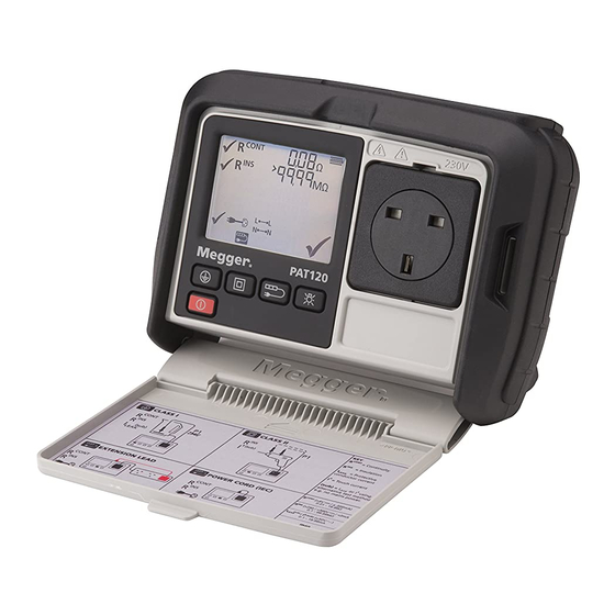
Page 7: Instrument Layout
Instrument Layout PAT120 Instrument Layout PAT150 Neck strap Neck strap slot slot Main test Main test socket socket Test groups Test groups Power ON – Hold for >0.5s Backlight Power ON – Quick test Setup Backlight Hold for >0.5s Display information PAT120... -
Page 8: Measurement Symbols
Measurement (display) symbols PAT120 & PAT150 PAT150 only Continuity of the protective earth Test in progress Residual current device test mode Test Probe P2 to be connected conductor 0˚ 0º - Positive edge test Insulation resistance between the current Measurement locked ON... -
Page 9: Instrument Buttons
RCD test button Connect the Instrument to the mains supply using the mains plug test lead (for mains powered leakage and RCD testing) Setup button – allows access to PASS limits, test times and lead null option Backlight button www.megger.com... -
Page 10: Carry Strap Fitting And Removal
Connect the P1 test lead to different conductive points on the equipment under test during the measurement Removing carry strap: Connect both the P1 and P2 test leads to the circuit to be measured Ensure equipment under test is switched ON www.megger.com... -
Page 11: Switching On / Off
Switching ON / OFF Switching ON iii) PAT120 >0.5 s Switching OFF Manual OFF Auto OFF Unit switches after 3 minutes of >2 s inactivity (not adjustable) Backlight Aborting a test A test can be aborted at any time by pressing the Power (ESC) button... -
Page 12: Class I Test (Pat120, 150) Using Substitute Leakage @ 40 V Ac
Class I test (PAT120, 150) using substitute leakage @ 40 V ac iii) Connect BOND lead P1 Class I @ 500 V Class I @ 250 V for IT equipment >2 s Ensure probe (P1) is connected Remove probe (P1) - Page 13 ) during a test for up to 3 minutes. To Lock R CONT ) or R ) on: CONT Press during the R ) or R ) test Press key again to unlock test and proceed to next test NOTE This feature is available in group test and QT mode. www.megger.com...
-
Page 14: Class I Test (Pat120, 150) Using Mains Leakage @ 230 V Ac
See Measurement symbols table. An L-N fault could damage the PAT tester and should be investigated. To override an L-N warning, press the Class I button. NOTE 3 : Faulty equipment may cause an RCD to trip during a Touch leakage test www.megger.com... -
Page 15: Class Ii Test (Pat120, 150) Using Substitute Leakage @ 40 V Ac
Class II test (PAT120, 150) using substitute leakage @ 40 V ac Battery powered testing of equipment without an Earth return conductor iii) Insulation test @ 500 V Insulation test @ 250 V >2 s Ensure probe (P1) is connected... -
Page 16: Class Ii Test (Pat120, 150) Using Mains Voltage Leakage @ 230 V Ac
High touch leakage measurement on faulty equipment can trip the supply RCD Warning : High inertia appliances (eg angle grinders) may present a hazard whilst running. It is recommended that where a hazard is likely, the battery powered "Substitute leakage" test is used, which will not operate the appliance. www.megger.com... -
Page 17: Power Cord Test (Pat120, 150)
Power cord test (PAT120, 150) Testing a standard power cord iii) Insulation test @ 500 V Insulation test @ 250 V >2 s NOTE For power cords longer than 5m the test can be re-run with a 1.0W pass limit by pressing the test button with 5 seconds of the continuity test failing –... -
Page 18: Extension Lead Test (Pat120, 150)
Extension lead test (PAT120, 150) Testing an extension lead or multi-way extension lead Insulation test @ 500 V Insulation test @ 250 V >2 s vii) NOTE: Multiple earth continuity tests can be carried out by pressing the QT button during the continuity test, and pressing it again for each new continuity test. See Page 13... -
Page 19: Portable Rcd Test (Pat150)
Press RESET on RCD viii) Press RESET on RCD Press RESET on RCD Test complete Note : The PAT150 defaults to 30 mA RCD. To change to 10 mA, hold the RCD button down for more than 2 seconds then release. www.megger.com... -
Page 20: Fixed Equipment Testing
Only a continuity test is possible when testing fixed equipment without disconnecting the incoming supply. Use the Quick Test (QT) button to access the continuity test mode: Ensure probe (P1) is connected iii) Press 5 times to display Continuity test vii) Test complete www.megger.com... -
Page 21: Fail Handling
Individual test fail indicated by a small cross: Overall FAIL indicated by a large cross: NOTE : Once an appliance has failed a test, further testing of the test group sequence is prevented for safety reasons, except for the extension lead testing www.megger.com... - Page 22 Insulation 250 V Substitute leakage (uses P1 probe) Extension Lead, Insulation 250 V Substitute Leakage Mains leakage (uses mains connection and P1 probe) Polarity (uses extension lead adaptor) Mains Leakage (needs mains connection) SELV measurement (uses P1 and P2 probes) www.megger.com...
-
Page 23: Quick Test Examples
Quick Test (QT) options Example 1- Class I continuity iii) CONT (sub) LEAK Example 2 – Class II 250 V Insulation test iii) www.megger.com... - Page 24 Example 3 – Class II touch leakage test using the Substitute (or alternative) method. iii) vii) To repeat test NOTE To switch between test groups, press the test group buttons. To exit press the ON/OFF button www.megger.com...
-
Page 25: Selv Measurement Within Quick Test (Qt)
SELV measurement within Quick Test (QT) Separated Extra Low Voltage (SELV) measurement is performed automatically when the PAT150 is connected to the electrical supply iii) vii) For voltages <50V ac For voltages ≥ 50V To exit Quick Test (QT) mode www.megger.com... -
Page 26: Setup (Pat120, Pat150)
0.30 MΩ 4th press Rins 6th press 0.50 MΩ 5th press l leak Note : Pressing QT changes the direction To SAVE changes to setup or, to edit new test groups When changes are complete press the Power button www.megger.com... -
Page 27: Continuity Lead Null
To NULL the resistance of the IEC test lead or an extension lead >2s IEC test lead NULL ON To remove the lead null >2s To NULL the resistance of the P1 continuity test lead >2s Continuity (P1) lest lead NULL ON To exit Lead null setup www.megger.com... -
Page 28: Rcd Configuration
Portable RCD trip time for 30 mA can be set at either 200 ms (for BS 7071 conformity) or 300 ms (for IEC 61540 conformity) Portable RCD trip current selection iii) Press RCD button to change from 30 mA to 10 mA For 10mA RCD To change trip time To exit RCD configuration www.megger.com... -
Page 29: Factory Reset To Default Settings
1xI∆N10 5xI∆N10 cont Variant Model (Ω) (sub), leak , I t (sub) (Ω) for Ext (ms) (ms) (ms) (ms) for RCD (MΩ) (MΩ) (MΩ) leak lead (mA) (mA) PAT120-UK 0.25 PAT150-UK 0.25 PAT120-DE, PAT120-CH, PAT120-EU PAT150-DE, PAT150-CH, PAT150-EU PAT150-AU www.megger.com... -
Page 30: Region Selection
Region selection i) To return an instrument to iii) Factory Default settings: Press together for 2 seconds www.megger.com... -
Page 31: International Model Variations
International model variations: Continuity retest after fail (PAT120, PAT150 DE, & CH models only) When a continuity test fails to meet the pre-set continuity resistance pass limit of 0.3 W, the test can be run again within 5 seconds at the higher 1.0 W limit. -
Page 32: Battery And Fuse Replacement (Pat120, 150)
Spent Alkaline and NiMH batteries are classified as portable batteries and should Warning: Only use a Megger approved PAT100 charger. Other chargers may present a fire be disposed of in the UK in accordance with risk. -
Page 33: Fuse Replacement
Spent PAT100 batteries are classified as Portable Batteries and should be disposed of in the UK in accordance with Local Authority requirements For disposal of batteries in other parts of the EU contact your local Megger company or distributor. Megger is registered in the UK as a producer of batteries. -
Page 34: Specification
+2% to +8% (1 x I, 5 x I) Reading corrected to 230V ac. Trip time accuracy ±1% ± 1 ms Trip time resolution 0.01 ms Display range 0 to 200 ms (1 x I) 0 to 40 ms (5 x I) MAINS SUPPLY TEST www.megger.com... - Page 35 CIRCUIT TEST 9.6 Vdc (NiMH AA LR6) (Carried out automatically, not available to user) Test voltage WEIGHT Test frequency Nominal Mains 50 Hz PAT120 (instrument only): 1150 g (40.4 oz) Test current < 100 mA short circuit Shipping weight: 2370g (83.6 oz)
- Page 36 Tel: +1 (214) 330-3203 (International) Fax: +1 (214) 337-3038 This instrument is manufactured in the United Kingdom. The company reserves the right to change the specification or design without prior notice. Megger is a registered trademark Part No. PAT100_UG_EN_V03 www.megger.com...
Need help?
Do you have a question about the PAT120 and is the answer not in the manual?
Questions and answers