
Subscribe to Our Youtube Channel
Related Manuals for Toro SprayMaster Max 34240


Summary of Contents for Toro SprayMaster Max 34240
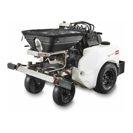
- Page 1 Form No. 3453-425 Rev A 46 and 52in Sprayer SprayMaster Max Model No. 34240—Serial No. 400000000 and Up Model No. 34242—Serial No. 400000000 and Up *3453-425* Register at www.Toro.com. Original Instructions (EN)
-
Page 2: Figure 1
Section 4442 or 4443 to use or operate the engine on additional information, contact an Authorized Service any forest-covered, brush-covered, or grass-covered Dealer or Toro Customer Service and have the model land unless the engine is equipped with a spark and serial numbers of your product ready. -
Page 3: Table Of Contents
Contents Cleaning .............. 53 Cleaning and Storing Safety ......53 Clean Engine and Exhaust System Safety ............... 4 Area .............. 53 Safety-Alert Symbol..........4 Remove Engine Shrouds and Clean Cooling General Safety ........... 4 Fins ............... 53 Safety and Instructional Decals ......5 Clean Debris From Machine ...... -
Page 4: Safety
General Safety Safety This machine is capable of amputating hands and The following instructions are from ANSI standard feet and of throwing objects. Always follow all safety B71.4-2017. instructions to avoid serious personal injury or death. • Read, understand, and follow all instructions Safety-Alert Symbol and warnings in the Operator’s Manual and on the machine, engine, and attachments. -
Page 5: Safety And Instructional Decals
• Replace all worn, damaged, or missing safety signs and instruction labels. They are critical signs. to the safe operation of your Toro commercial • When replacement components are installed, be spreader-sprayer. sure that current safety signs are affixed to the replaced components. - Page 6 decal142-9684 142-9684 decal135-6728 135-6728 1. Indicator settings 3. Heavy on right side 1. Press and hold foot button 2. Release foot button to shut 2. Spread pattern control 4. Heavy on left side to turn on spray. off spray. knob decal142-8079 142-8079 1.
- Page 7 decal142-5588 142-5588 1. Spread pattern control–Rotate clockwise if heavy on left side 6. Rate dial–least material distributed 2. Spread pattern control–Rotate counterclockwise if heavy on 7. Rate dial–maximum material distributed right side 3. Spread On–Pull handle up 8. Deflector–Pull knob up to open 4.
- Page 8 decal146-0776 146-0776...
- Page 9 decal142-8040 142-8040 1. Read the instructions before servicing or performing 5. Check tire and caster wheel pressure (4 locations). maintenance. 2. Time interval. 6. Grease idler pivot; refer to the Operator’s Manual for further instructions. 3. Check engine oil level. 7.
- Page 10 decal146-0162 146-0162 21. Reverse 1. Spray pressure decrease 2. Spray pressure increase 22. Warning—Read the Operator’s Manual; Do Not operate this machine unless you are trained. Wear hearing protection. 3. Left nozzle spray-Off 23. Thrown object hazard-Keep bystanders away. 4. Left nozzle spray-On 24.
-
Page 11: Product Overview
Controls Product Overview Become familiar with all the controls before you start the engine and operate the machine. Machine Controls Become familiar with all the controls before starting the engine and operating the machine. Motion Control Levers The motion control levers, located on each side of the top console, control the forward and reverse motion of the machine. - Page 12 START. Insert key into switch and rotate clockwise to the ON position. Rotate clockwise to the next position to engage the starter (key must be held against spring pressure in this position). Allow the key to return to the ON position immediately after the engine starts. Note: The parking brake must be engaged and the motion-control levers in neutral to start the engine.
- Page 13 gauge (decreasing pressure from gauge will increase agitation in the tank). Spray Pump Foot Button Located on the left side of the operator platform. Press and hold the foot button to turn the sprayer system pump to ON. Release the foot button to turn the sprayer system pump to OFF.
- Page 14 Rotate the handle clockwise to reel the hose in. Rotate The valving options allow product to be pulled from the handle counterclockwise to release the hose. both tanks simultaneously or independently. Rotate the handles counterclockwise to turn on the valves (open position) and clockwise to turn it off (close position).
- Page 15 g393058 Figure 9 Hopper Console g312556 1. Spread pattern control 4. Rate dial Figure 10 knob 2. Digital display gauge 5. Deflector control 1. Fence 3. Side deflector lowered 3. Spread gate Open/Close 2. Flowers Rate Dial Spread Pattern Control Knob Located on the hopper console to the right of the Located on the left side of the hopper console and is digital display gauge (reference...
- Page 16 g387110 Figure 11 g395205 Figure 12 1. Caster pin locking mechanism 1. Slot in Bypass (released) 2. Slot in Run (operating) position position Drive Wheel Release Valves To release the drive system (see item 1 in Figure 12), rotate the slot a quarter-turn clockwise. WARNING To reset the drive system (see item 2 in Figure...
-
Page 17: Specifications
Specifications 46-inch sprayer: 117 cm (46 inches) Overall width 52-inch sprayer: 132 cm (52 inches) 46-inch sprayer: 185 cm (73 inches) Overall length 52-inch sprayer: 183 cm (72 inches) Overall height 127 cm (50 inches) 46-inch sprayer: 406 kg (896 lb) Sprayer tank and hopper empty 52-inch sprayer: 414 kg (912 lb) 46-inch sprayer: 520 kg (1,146 lb) -
Page 18: Before Operation
Do not operate the machine unless they are in proper working condition. Replace worn or deteriorated parts with genuine Toro parts when necessary. DANGER It is essential that operator safety mechanisms be connected and in proper operating condition prior to use. - Page 19 Chemical Safety Fuel Safety DANGER WARNING Gasoline is extremely flammable and vapors Chemical substances used in the are explosive. spreader-sprayer system may be hazardous and toxic to you, bystanders, animals, plants, A fire or explosion from gasoline can burn soils or other property. you, others, and cause property damage.
-
Page 20: Fuel Specification
During Operation on a truck or trailer from a portable container, rather than from a gasoline dispenser nozzle. – If a gasoline dispenser nozzle is used, keep During Operation Safety the nozzle in contact with the rim of the fuel tank or container opening at all times until fueling is complete. - Page 21 • Start the engine with your feet well away from the – Never allow children to operate the machine. spreader or spray nozzles. – Do not carry children, even with the • Be aware of weather conditions and check that spreading/spraying shut off.
- Page 22 over the edge or the edge collapses. Keep a safe WARNING distance (twice the width of the machine) between Spray wand traps liquids under high the machine and any hazard. Use a walk-behind pressure, even when engine is off. High machine or a handheld tool to operate in these pressure spray discharge could cause areas.
-
Page 23: Operating The Machine
Operating the Machine (pushed forward) before the motion control lever can be moved. Starting the Engine Leave the motion control levers in neutral and engage the parking brake. Set the throttle to the FAST position. On a cold engine, push the choke lever forward into the ON position. - Page 24 To stop, position both motion control levers in the neutral position; releasing the lever will automatically return it to neutral. Note: Stopping distance may vary depending on the spreader-sprayer load. Driving in Reverse Move the motion control lever to the neutral position.
-
Page 25: Operating The Spreader
Before Operating the Spreader Make sure the spreader has been calibrated for the material to be spread before starting; refer to Spreader Calibration (page 27). Important: Verify that the proper application rate has been set prior to filling the hopper. Filling the Spreader Hopper Stop the machine on a level surface, move motion control lever to the neutral position, stop... - Page 26 Cleaning the Spreader Pull the Spread Open/Close handle up to open the hopper gate and begin spreading. Drive the machine to a designated cleaning area. Stop the machine on a level surface, leave the motion control lever in the neutral position, and turn off the engine.
- Page 27 Determining the Distribution Pattern Operator supplied equipment: 15 shallow collection pans and 15 graduated measuring cylinders The most accurate method to measure the distribution is to use shallow collection pans and graduated measuring cylinders. In the example below, 15 shallow collection pans approximately 30 cm (12 inches) wide, 91 cm (36 inches) long, and 5 cm (2 inches) tall are used.
- Page 28 Determining the Effective Spreading Width The effective width is used to determine the uniform distribution of the material. Note: The spreading width range is 0.9 m (3 ft) up to 7.6 m (25 ft). After the spreader pattern is correctly adjusted, evaluate the amount of material in the center graduated measuring cylinder.
-
Page 29: 93 M 2 (1,000 Ft 2 )
Empty the remaining material of the hopper into a clean bucket. Weigh the bucket containing the material and record the weight. Pour the contents back into the hopper and then weigh the empty bucket. Subtract these two amounts to determine the amount of material remaining in the hopper (for example, 9 kg (20 lb) remains.) Subtract the amount remaining in the hopper... - Page 30 Spread Gate Opening Adjustment Rotate the nut to increase or decrease tension. Make sure the Spread Gate Open/Close knob is in the closed position. g394297 Figure 27 1. Rate dial 3. Nut 2. 28 mm (1.12 inches) Spread Pattern Control Tension Adjustment If the Spread Pattern Control (diffuser) will not stay in the set location, increase the tension.
- Page 31 Spread Gate Open/Close Tension Adjustment If the Spread Gate Open/Close linkage will not stay in the open or closed position, adjust the tension. Tighten the nut in small increments, on the right side of the hopper assembly, to increase the tension; to decrease the tension, loosen the nut.
-
Page 32: Lb (0.45 Kg)
g394483 Figure 31 1. Rate gate knob 3. Gap 2. Bottom of the rate dial 4. Rate gate stop Spreading Charts Note: The Dial Settings chart and the Grass Seed Spreading chart are provided with permission from the Brinly-Hardy Company; reference the Brinly-Hardy Company website for more information. These charts are to be used as an approximate guideline only. -
Page 33: Operating The Sprayer
The chart below is for reference only. When spraying and spreading at the same time, set the spread pattern to twice the width of the spray; this will help avoid striping and streaking. For example, standard spray width = 2.7 m (9 ft) and spread width = 5.4 m (18 ft). - Page 34 Important: The tank markings are for reference increase circulation/agitation and help purge only and cannot be considered accurate for the system of air. calibration. Add the proper amount of chemical concentrate Stop the machine on a level surface, move to the tank, as directed by the chemical motion control lever to the neutral position, stop manufacturer.
- Page 35 g387108 g387134 Figure 36 Figure 34 1. Left tank return valve 3. Right tank suction valve 1. Left tank return valve 3. Right tank suction valve (open position) (open position) (open position) (close position) 2. Left tank suction valve 4. Right tank return valve 2.
- Page 36 • Better results are obtained if the sprayer is moving Remove the wand from the holder on the when spray controls are turned on. right side of the machine. • Watch for changes in the application rate that may Turn the spray wand flow valve on. indicate that your speed has changed beyond the Firmly grip and hold the spray wand.
- Page 37 Drive the machine to a designated cleaning Repeat steps through 13. area. Using a garden hose, spray off the outside of the Stop the spreader-sprayer on a level surface, sprayer tank with clean water. leave the motion control lever in the neutral Note: Do Not use a power washer to clean position, and turn off the engine.
- Page 38 Spray Calibration/Tip Chart/Liquid Quantities Note: Before using the sprayer for the first time, change nozzles, or as needed–calibrate the sprayer flow and speed. Note: Refer to the chemical product label for application rate recommendations. The lavender colored air injected tips come standard on the machine. These tips will apply liquid material at 1.24 L (0.34 US gallons) per 93 m (1,000 ft ) at 8 km/h (5 mph) and 276 kPa (40 psi).
-
Page 39: After Operation
After Operation After Operation Safety General Safety • Park machine on level ground, disengage drives, set parking brake, stop engine, and remove key. Wait for all moving parts to stop before leaving the operator’s position. Allow the machine to cool before servicing, adjusting, fueling, cleaning, or storing. - Page 40 wide enough to extend beyond the rear tires is recommended instead of individual ramps for each side of the machine. A full width ramp provides a surface to walk on behind the machine. If it is not possible to use one full width ramp, use enough individual ramps to simulate a full width continuous ramp.
-
Page 41: Maintenance
Unauthorized modifications to the original equipment or failure to use original Toro parts could lead to serious injury or death. Unauthorized changes to the machine, engine, fuel or venting system, may violate applicable... -
Page 42: Recommended Maintenance Schedule(S)
Recommended Maintenance Schedule(s) Maintenance Service Maintenance Procedure Interval • Change the engine oil. After the first 5 hours • Check the wheel mount screw torque specification. After the first 100 hours • Change hydraulic system filter and fluid. • Check air cleaner; replace if dirty. (May need more often under severe conditions.) •... -
Page 43: Notation For Areas Of Concern
Notation for Areas of Concern Inspection performed by: Item Date Information Important: Refer to your engine owner’s manual for additional maintenance procedures. -
Page 44: Lubrication
Lubrication Engine Maintenance Service Air Cleaner Lubricate Grease Fittings Service Interval: Before each use or daily—Check Service Interval: Every 100 hours/Yearly (whichever air cleaner; replace if dirty. (May comes first) need more often under severe Every 100 hours/Yearly (whichever comes first) conditions.) Every 100 hours/Yearly (whichever comes Note:... -
Page 45: Fuel System Maintenance
Fuel System thin coating of engine oil on the surface of the rubber seal. Turn filter clockwise until rubber Maintenance seal contacts the filter adapter then tighten filter an additional 1/2 to 3/4 turn. Clean around oil fill cap and remove cap. Fill to Check Fuel Filter and Tank specified capacity and replace cap. -
Page 46: Electrical System Maintenance
Charge batteries in an open well ventilated area, batteries with an output of 3.5 amps or less. away from spark and flames. Unplug charger before Toro recommends the use of battery charger connecting or disconnecting from battery. Wear P/N 135-7024. Make sure the negative battery protective clothing and use insulated tools. - Page 47 DANGER Jump starting a weak battery that is cracked, frozen, has low electrolyte level, or an open/shorted battery cell, can cause an explosion resulting in serious personal injury. Do not jump start a weak battery if these conditions exist. Make sure the booster is a good and fully g012785 Figure 41 charged lead acid battery at 12.6 V or greater.
-
Page 48: Drive System Maintenance
Belt Maintenance Drive System Maintenance Check Condition of Belt Check Tire Pressures Service Interval: Every 40 hours Stop engine, wait for all moving parts to stop, Service Interval: Every 50 hours and remove key. Engage parking brake. Stop engine, wait for all moving parts to stop, Check the belt condition and tension. -
Page 49: Controls System Maintenance
Controls System Engage the park brake and check. If more adjustment are needed, repeat steps and 6. Maintenance Retighten the jam nuts. Install the left rear hydro cover. Adjusting the Parking Motion Control Linkage Brake Adjustment If the parking brake does not hold securely, an adjustment is required. -
Page 50: Motion Control Tracking Adjustment
Replace the knee pad. Repeat steps through until desired tracking is obtained. g387366 Figure 44 Right Motion Control Linkage Shown 1. Upper jam nut 3. Control rod 2. Jam nuts Retighten the jam nuts on the control rod. Replace the knee pad. Motion Control Tracking Adjustment If the machine travels or pulls to one side when the... -
Page 51: Hydraulic System Maintenance
With the hopper empty, tip the hopper forward. Hydro Oil Service Interval Clean area around oil overflow tank and remove Toro Hypr-Oil 500 After first 100 hours cap. Oil level should be at the FULL COLD line; *Every 400 hours thereafter if not, add hydraulic oil. -
Page 52: Maintaining The Chassis
Maintaining the Chassis pump. If wheels rotate slowly, the system may prime after additional running. Check oil level as described in Check Hydraulic Oil and Tank Level (page 51). Check for Loose Hardware Allow the machine to run several minutes Service Interval: Before each use or daily after the charge pumps are “primed”... -
Page 53: Maintaining The Sprayer And Spreader Systems
Maintaining the Sprayer Cleaning and Spreader Systems Cleaning and Storing Safety Check Spreader System • Park machine on level ground, disengage drives, set parking brake, stop engine, and remove key. Wait for all moving parts to stop before leaving Service Interval: Every 50 hours the operator’s position. -
Page 54: Clean Debris From Machine
Battery Disposal Remove cooling shrouds from engine and clean cooling fins. Also clean dust, dirt, and oil from external surfaces of engine which can cause DANGER improper cooling. Battery electrolyte contains sulfuric acid, Make sure cooling shrouds are properly which is poisonous and can cause severe reinstalled. -
Page 55: Storage
Storage Extended or Winter Storage To help protect the pumps from freezing temperatures make sure the unit is free of all caustic chemicals and residue. Spreader Cleaning Perform all the steps in Cleaning the Spreader (page in the Operation section. Sprayer Cleaning Perform all the steps in Cleaning the Sprayer... -
Page 56: Troubleshooting
Troubleshooting Important: It is essential that all operator safety mechanisms be connected and in proper operating condition prior to use. Important: When troubleshooting or replacing electrical components, disconnect the capacitor harness from the main harness before performing any maintenance. When a problem occurs, do not overlook the simple causes. For example: starting problems could be caused by an empty fuel tank. - Page 57 Problem Possible Cause Corrective Action Engine overheats 1. Engine load is excessive 1. Reduce the ground speed. 2. Oil level in the crankcase is low. 2. Add oil to the crankcase. 3. Cooling fins and air passages for the 3. Remove the obstructions from the engine are plugged.
- Page 58 Problem Possible Cause Corrective Action Spray wand does not work. 1. Tank is empty. 1. Fill tank. 2. Control valve in wrong position. 2. Place in “open” position. 3. Wand is clogged or damaged. 3. Clean, repair, or replace wand. 4.
-
Page 59: Schematics
Schematics g402879 Electrical Schematic (Rev. B) - Page 60 While the exposure from Toro products may be negligible or well within the “no significant risk” range, out of an abundance of caution, Toro has elected to provide the Prop 65 warnings. Moreover, if Toro does not provide these warnings, it could be sued by the State of California or by private parties seeking to enforce Prop 65 and subject to substantial penalties.
Need help?
Do you have a question about the SprayMaster Max 34240 and is the answer not in the manual?
Questions and answers