Table of Contents
Advertisement
Advertisement
Table of Contents

Related Manuals for Inovance MD200S0.4B


Summary of Contents for Inovance MD200S0.4B
- Page 1 User Guide MD200 Series AC Drive User Guide Data code 19010397...
-
Page 2: Revision History
■ This user guide is shipped with the product. For any question or query, contact your sales representative. ■ To obtain the user guide, access Inovance's website (http://www.inovance.com), click "Download", search for the user guide by its name, and then download the PDF file. -
Page 3: Safety Instructions
4) Use this equipment according to the designated environment requirements. Damage caused by improper usage is not covered by warranty. 5) Inovance shall take no responsibility for any personal injuries or property damage caused by improper usage. Safety Levels and Definitions... - Page 4 Safety Instructions WARNING ◆ Do not install the equipment if you find damage, rust, or indications of use on the equipment or accessories. ◆ Do not install the equipment if you find water seepage, component missing or damage upon unpacking. ◆...
- Page 5 Safety Instructions DANGER ◆ Equipment installation, wiring, maintenance, inspection, or parts replacement must be performed only by professionals. ◆ Installation, wiring, maintenance, inspection, or parts replacement must be performed only by experienced personnel who have been trained with necessary electrical information.
- Page 6 Safety Instructions Power-on DANGER ◆ Before power-on, make sure that the equipment is installed properly with reliable wiring and the motor can be restarted. ◆ Before power-on, make sure that the power supply meets equipment requirements to prevent equipment damage or even a fire. ◆...
- Page 7 Safety Instructions WARNING ◆ Perform daily and periodic inspection and maintenance for the equipment according to maintenance requirements and keep a maintenance record. Repair DANGER ◆ Equipment installation, wiring, maintenance, inspection, or parts replacement must be performed only by professionals. ◆...
-
Page 8: Safety Signs
Safety Instructions Safety Signs ■ Description of safety signs in the user guide Read the user guide before installation and operation. Reliably ground the system and equipment. Danger! High temperature! Prevent personal injuries caused by machines. High voltage! Wait xx minutes before further operations. **min ■... -
Page 9: Table Of Contents
Contents Contents Revision History ......................... 1 Safety Instructions ........................2 Safety Precautions ....................... 2 Safety Levels and Definitions ..................... 2 Safety Instructions ....................... 2 Safety Signs .......................... 7 1 Product Overview ........................10 1.1 Product Information ....................10 1.2 Panel Operations ......................11 2 Installation and Wiring ...................... - Page 10 Contents ....................... 78 5.4.2 External Filter 5.5 Selection of the AC Input Reactor ................82 5.6 Selection of the dv/dt Output Reactor ............... 82 5.7 Selection of Cables and Tightening Torque............... 84 5.8 Selection of Optionals ....................85 - 9 -...
-
Page 11: Product Overview
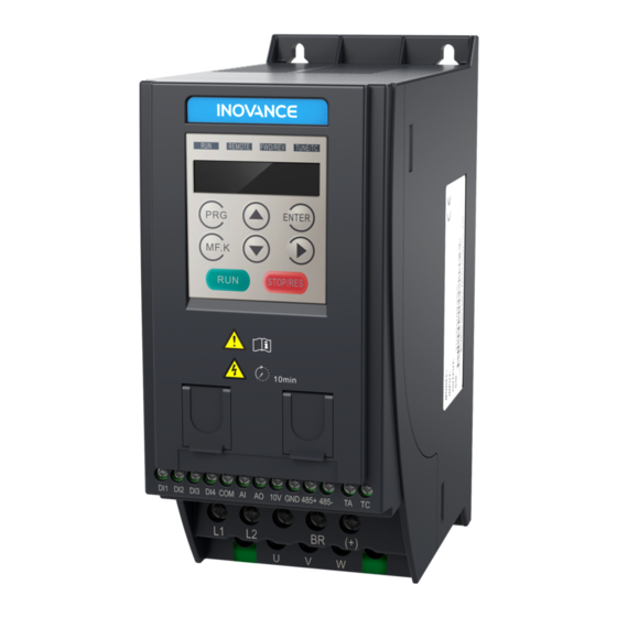
1 Product Overview Thank you for purchasing the MD200 series AC drive developed by Inovance. With the compact booksize structure design, the MD200 series AC drive allows seamless parallel installation and guide rail installation, featuring small size and simplified installation. The wiring terminals are uncovered, simplifying wiring, operation, and maintenance. -
Page 12: Panel Operations
1 Product Overview 1.2 Panel Operations Quick commissioning flowchart: Steps Operations Power on the AC drive. ENTER ENTER Set the frequency source. Operating panel Select the frequency ENTER reference setting channel. Digital setting ENTER Set the frequency. ENTER Return to the frequency reference display. -
Page 13: Installation And Wiring
2 Installation and Wiring 2 Installation and Wiring 2.1 Installation The AC drive must be installed in a fireproof cabinet with doors that provide effective electrical and mechanical protection. The installation must conform to local and regional laws and regulations, and relevant IEC requirements. 2.1.1 Layout in the Cabinet ≥... -
Page 14: Installation Method
2 Installation and Wiring 2.1.2 Installation Method 4 x M4 x 16 cross recessed pan head screws With screws Bracket slot of guide rail Bracket slot of guide rail With a guide rail ◆ To install the AC drive with screws, all the four screws must be tightened. ◆... -
Page 15: Installation Environment
2 Installation and Wiring 2.1.2 Installation Environment 1) Ambient temperature: The AC drive's service life is greatly influenced by the ambient temperature. Do not run the AC drive under a temperature exceeding the allowed temperature range (-10℃ to +50℃ ). 2) Install the AC drive on a flame-retardant surface, and ensure that sufficient space is left around the enclosure to allow for efficient heat dissipation. -
Page 16: Wiring
2 Installation and Wiring 2.2 Wiring 2.2.1 Wiring Diagrams ■ MD200XXX wiring diagram Recommended Recommended AC Drive Model AC Drive Model Resistance Resistance MD200T3.7B 130 Ω/400 W MD200S2.2B 70 Ω/100 W MD200T2.2B 200 Ω/300 W MD200S1.5B 100 Ω/100 W MD200T1.5B 220 Ω/250 W MD200S0.75B 150 Ω/80 W... - Page 17 2 Installation and Wiring ■ MD200XXX-NC wiring diagram Recommended Recommended AC Drive Model AC Drive Model Resistance Resistance MD200T3.7B-NC 130 Ω/400 W MD200S2.2B-NC 70 Ω/100 W MD200T2.2B-NC 200 Ω/300 W MD200S1.5B-NC 100 Ω/100 W MD200T1.5B-NC 220 Ω/250 W MD200S0.75B-NC 150 Ω/80 W MD200T0.75B-NC 300 Ω/150 W MD200S0.4B-NC...
-
Page 18: Terminal Specifications
2 Installation and Wiring 2.2.2 Terminal Specifications Terminal Terminal Terminal Name Terminal Function Type Mark Single-phase Connected to the power supply. L1 is connected to the live L1, L2 power supply wire and L2 is connected to the neutral wire. input Three-phase R, S, T... -
Page 19: Wiring Of Control Signal Input Terminals
2 Installation and Wiring Terminal Terminal Terminal Name Terminal Function Type Mark Common ground with 10 V RS485 positive Half duplex RS485 communication, with Control 485+ communication Communication the highest baud rate of 115200 for up circuit signal to 64 nodes RS485 negative Note: The RS485 communication 485-... - Page 20 2 Installation and Wiring ■ Sink wiring method +24V DIP switch set to ON +VCC Signal DI valid value: 0 V External NPN type (default) External AC drive controller control board Figure 2-6 Sink wiring In such wiring mode, the DI terminals of different AC drives cannot be connected in parallel.
- Page 21 2 Installation and Wiring ■ Source wiring method +24V DI valid value: 24 V Signal External PNP type DIP switch set to OFF External AC drive controller control board Figure 2-8 Source wiring ■ DO terminals When the DO terminal needs to drive the relay, a snubber diode shall be installed on both sides of the relay coil.
- Page 22 2 Installation and Wiring 220 VAC 24 VDC Figure 2-10 Anti-interference processing of relay output terminals ◆ Wiring tools: Phillips head screwdriver or straight screwdriver; main circuit terminal screw ≥ M4; control circuit terminal ≥ M3 ◆ It is recommended that L1 be connected with the live wire and L2 be connected with the neutral wire.
-
Page 23: Parameters
3 Parameters 3 Parameters 3.1 Parameter Table If FP-00 is set to a non-zero value (which enables password protection), the parameter menu is accessible in base mode and modification mode only after the correct password is entered. To disable password protection, set FP-00 to 0. Groups F and A include standard function parameters. - Page 24 3 Parameters Param. Communication Param. Name Setting Range Default Address Base value of range of auxiliary frequency 0: Relative to the maximum frequency F0-05 0xF005/0x0005 reference for main 1: Relative to main frequency reference X and auxiliary superposition Range of auxiliary frequency F0-06 reference for main...
- Page 25 3 Parameters Param. Communication Param. Name Setting Range Default Address Model F0-15 Carrier frequency 0.8 kHz to 12.0 kHz 0xF00F/0x000F dependent Carrier frequency 0: No F0-16 adjusted with 0xF010/0x0010 1: Yes temperature 0.00s to 650.00s (F0-19 = 2) F0-17 Acceleration time 1 0.0s to 6500.0s (F0-19 = 1) 20.0s 0xF011/0x0011...
- Page 26 3 Parameters Param. Communication Param. Name Setting Range Default Address Asynchronous 0.01 A to F1-03 (AC drive power ≤ 55 Auto- F1-10 motor no-load tuning 0xF10A/0x010A current 0.1 A to F1-03 (AC drive power > 55 kW) parameter 0: No operation 1: Asynchronous motor static auto- Auto-tuning F1-37...
- Page 27 3 Parameters Param. Communication Param. Name Setting Range Default Address 0: Set by F2-09 (Torque limit source in speed control) and F2-10 (Digital setting of torque limit in speed control) 1: AI 2: External operating panel potentiometer 4: Pulse reference Torque limit source 5: Communication setting F2-11...
- Page 28 3 Parameters Param. Communication Param. Name Setting Range Default Address Group F3: V/f Control Parameters 0: Linear V/f 1: Multi-point V/f F3-00 V/f curve setting 0xF300/0x0300 10: V/f complete separation mode 11: V/f half separation 0.0%: Automatic torque boost F3-01 Torque boost 0.0% 0xF301/0x0301 0.1% to 30.0%...
- Page 29 3 Parameters Param. Communication Param. Name Setting Range Default Address 0: Frequency and voltage declining to 0 Stop mode independently F3-17 selection for V/f 0xF311/0x0311 1: Frequency declining after voltage separation declines to 0 F3-18 Current limit level 50% to 200% 150% 0xF312/0x0312 Current limit...
- Page 30 3 Parameters Param. Communication Param. Name Setting Range Default Address Frequency rise F3-26 threshold during 0 to 50 Hz 5 Hz 0xF31A/0x031A voltage limit AC drive bus voltage limit (and braking resistor applied voltage settings) When the bus voltage rises above the voltage limit 390 V, the motor becomes regenerative (motor speed >...
- Page 31 3 Parameters Param. Communication Param. Name Setting Range Default Address Group F4: Input Terminals DI1 function 0: No function F4-00 0xF400/0x0400 1: Forward RUN (FWD) or running command selection 2: Reverse RUN (REV) or running direction DI2 function (When these parameters are set to values 1 F4-01 0xF401/0x0401 selection...
- Page 32 3 Parameters Param. Communication Param. Name Setting Range Default Address 0: Two-wire mode 1 Terminal command 1: Two-wire mode 2 F4-11 0xF40B/0x040B mode 2: Three-wire mode 1 3: Three-wire mode 2 Terminal UP/DOWN F4-12 0.001 Hz/s to 65.535 Hz/s 1.000 Hz/s 0xF40C/0x040C change rate AI curve 1 minimum...
- Page 33 3 Parameters Param. Communication Param. Name Setting Range Default Address Ones position: AI curve selection 1: Curve 1 (2 points, see F4-13 to F4-16) 2: Curve 2 (2 points, see F4-18 to F4-21) F4-33 AI curve selection 0xF421/0x0421 Tens position: External operating panel potentiometer curve selection, same as above Ones position: Setting for AI less than...
- Page 34 3 Parameters Param. Communication Param. Name Setting Range Default Address Group F5: Output Terminals 0: No output 19: Undervoltage 1: AC drive running state output 2: Fault output (stop Control board relay upon fault) Communication F5-02 function selection 0xF502/0x0502 3: Frequency-level setting (TA/TB/TC) detection 1 output...
- Page 35 3 Parameters Param. Communication Param. Name Setting Range Default Address 0: Running frequency 1: Frequency reference 2: Output current 3: Motor output torque (absolute value) 4: Output power 5: Output voltage 6: Pulse input (100.0% corresponding to 20.00 kHz) 7: AI AO function 8: External operating panel F5-07...
- Page 36 3 Parameters Param. Communication Param. Name Setting Range Default Address Startup frequency F6-04 0.0s to 100.0s 0.0s 0xF604/0x0604 active time 0: Linear acceleration/deceleration Acceleration/ F6-07 2: Dynamic S-curve acceleration/ 0xF607/0x0607 Deceleration mode deceleration Time proportion F6-08 of S-curve start 0.0% to (100.0% – F6-09) 30.0% 0xF608/0x0608 segment...
- Page 37 3 Parameters Param. Communication Param. Name Setting Range Default Address 0: STOP/RES key enabled only in STOP/RES key operating panel control F7-02 0xF702/0x0702 function 1: STOP/RES key enabled in any operation mode 0000 to FFFF Bit00: Running frequency (Hz) Bit01: Frequency reference (Hz) Bit02: Bus voltage (V) Bit03: Output voltage (V) Bit04: Output current (A)
- Page 38 3 Parameters Param. Communication Param. Name Setting Range Default Address 0000 to 1FFF Bit00: Frequency reference (Hz) Bit01: Bus voltage (V) Bit02: DI state Bit03: DO state Bit04: AI1 voltage (V) Bit05: Reserved LED display stop F7-05 Bit06: External operating panel 0033 0xF705/0x0705 parameters...
- Page 39 3 Parameters Param. Communication Param. Name Setting Range Default Address Jog acceleration F8-01 0.0s to 6500.0s 20.0s 0xF801/0x0801 time Jog deceleration F8-02 0.0s to 6500.0s 20.0s 0xF802/0x0802 time F8-03 Acceleration time 2 0.0s to 6500.0s 20.0s 0xF803/0x0803 F8-04 Deceleration time 2 0.0s to 6500.0s 20.0s 0xF804/0x0804 F8-07 Acceleration time 4 0.0s to 6500.0s...
- Page 40 3 Parameters Param. Communication Param. Name Setting Range Default Address Detection width of F8-31 0.0% to 100.0% (maximum frequency) 0.0% 0xF81F/0x081F frequency 0.0% to 300.0% Zero current F8-34 The value 100.0% corresponds to the 5.0% 0xF822/0x0822 detection level rated motor current. Zero current F8-35 0.01s to 600.00s...
- Page 41 3 Parameters Param. Communication Param. Name Setting Range Default Address This parameter is used to set the speed synchronous control function. The speed synchronous control function is to enable direct data communication between two or more MD200 AC drives using CANlink for synchronizing the target frequency of one or more slaves with the target frequency of the master.
- Page 42 3 Parameters Param. Communication Param. Name Setting Range Default Address 115% of the rated motor current and the motor runs at this level for 80 minutes, Err11 (motor overload) is detected. Example: The rated motor current is 100 A. If F9-01 (Motor overload protection gain) is set to 1.00, when the motor running current reaches 125 A (125% of 100 A) and the motor runs at 125 A for 40 minutes, the AC drive reports Err11 (motor overload).
- Page 43 3 Parameters Param. Communication Param. Name Setting Range Default Address Output phase loss 0: Disabled F9-13 0xF90D/0x090D protection 1: Enabled 0: No fault 19: Motor auto- 1: Reserved tuning abnormal 2: Overcurrent 20: Reserved during acceleration 21: Parameter 3: Overcurrent read/write during deceleration abnormal...
- Page 44 3 Parameters Param. Communication Param. Name Setting Range Default Address AC drive state upon F9-22 – – 0xF916/0x0916 3rd (latest) fault Power-on time F9-23 upon 3rd (latest) – – 0xF917/0x0917 fault Running time upon F9-24 – – 0xF918/0x0918 3rd (latest) fault Frequency upon F9-27 –...
- Page 45 3 Parameters Param. Communication Param. Name Setting Range Default Address Ones position: Motor overload (11) 0: Coast to stop 1: Stop according to the stop mode 2: Continue to run Fault protection Tens position: Input phase loss (12) F9-47 0xF92F/0x092F action selection Hundreds position: Output phase loss (13)
- Page 46 3 Parameters Param. Communication Param. Name Setting Range Default Address Backup frequency 0.0% to 100.0% (maximum frequency, F9-55 100.00% 0xF937/0x0937 upon abnormality F0-10) Power dip ride- 0: Disabled F9-59 through function 1: Decelerate 0xF93B/0x093B selection 2: Decelerate to stop Threshold of power F9-60 dip ride through 80% to 100% (standard bus voltage)
- Page 47 3 Parameters Param. Communication Param. Name Setting Range Default Address Threshold of bus voltage Power dip ride through recovering from power dip F9-60 Threshold of power dip ride- through function enabled F9-62 voltage Time (t) Output frequency Time (t) Power dip ride Judging time of bus voltage through recovering from power dip...
- Page 48 3 Parameters Param. Communication Param. Name Setting Range Default Address 0: Set by FA-01 (PID digital reference) 1: AI 2: External operating panel PID reference FA-00 potentiometer 0xFA00/0x0A00 setting channel 4: Pulse reference (DI4) 5: Communication setting 6: Multi-reference PID digital FA-01 0.0% to 100.0% 50.0%...
- Page 49 3 Parameters Param. Communication Param. Name Setting Range Default Address FA-05 (Proportional gain Kp1): It decides the regulating intensity of the PID function. The larger the Kp1 is, the greater the regulating intensity will be obtained. When this parameter is set to 1000.0, the deviation between PID feedback and PID setting is 1000.0%.
- Page 50 3 Parameters Param. Communication Param. Name Setting Range Default Address 0: No switchover 1: Switchover by DI PID parameter 2: Automatic switchover based on FA-18 switchover 0xFA12/0x0A12 deviation condition 3: Automatic switchover based on running frequency PID parameter 0.0% to FA-20 (PID parameter switchover FA-19 switchover 20.0%...
- Page 51 3 Parameters Param. Communication Param. Name Setting Range Default Address When the AC drive starts up, the PID starts closed-loop algorithm only after the PID output is fixed to the PID initial value (FA-21) and lasts the time set by FA-22. PID initial value function This function limits the difference between two PID outputs (at an interval of 2 ms) to avoid quick PID output change and stabilize the AC drive running.
- Page 52 3 Parameters Param. Communication Param. Name Setting Range Default Address These parameters are used to check whether the PID feedback is lost. If the PID feedback is lower than the value of FA-26 and the lasting time exceeds the value of FA-27, the AC drive reports Err31 and acts according to the selected fault protection action.
- Page 53 3 Parameters Param. Communication Param. Name Setting Range Default Address Acceleration/ Deceleration time FC-19 0 to 1 0xFC13/0x0C13 of simple PLC reference 0 Running time FC-20 of simple PLC 0.0s (h) to 6500.0s (h) 0.0s(h) 0xFC14/0x0C14 reference 1 Acceleration/ Deceleration time FC-21 0 to 1 0xFC15/0x0C15...
- Page 54 3 Parameters Param. Communication Param. Name Setting Range Default Address Running time FC-32 of simple PLC 0.0s (h) to 6500.0s (h) 0.0s(h) 0xFC20/0x0C20 reference 7 Acceleration/ Deceleration time FC-33 0 to 1 0xFC21/0x0C21 of simple PLC reference 7 Time unit of simple 0: s (second) FC-50 0xFC32/0x0C32...
- Page 55 3 Parameters Param. Communication Param. Name Setting Range Default Address The following table describes the difference between the non-standard and standard Modbus protocols. Non-standard Modbus Protocol (Fd-05 = 0) Standard Modbus Protocol (Fd-05 = 1) Byte number high order 00H Byte number Byte number low order Data F002H high order...
- Page 56 3 Parameters Param. Communication Param. Name Setting Range Default Address User-defined FE-12 F0.00 0xFE0C/0x0E0C parameter 12 User-defined FE-13 F0.00 0xFE0D/0x0E0D parameter 13 User-defined FE-14 F0.00 0xFE0E/0x0E0E parameter 14 User-defined FE-15 F0.00 0xFE0F/0x0E0F parameter 15 User-defined FE-16 F0.00 0xFE10/0x0E10 parameter 16 User-defined FE-17 F0.00...
- Page 57 3 Parameters Param. Communication Param. Name Setting Range Default Address 0: No operation 01: Restore factory parameters except motor parameters 02: Clear records 03: Reserved Industry macro 04: Back up current user parameters FP-01 0x1F01 instruction 05 to 19: Reserved 20: Mechanical moving (conveyor belt) industry 21: Inertia (fan) industry...
- Page 58 3 Parameters Param. Communication Param. Name Setting Range Default Address Group A1: Function setting for AI used as DI A1-00 Reserved 0xA100/0x4100 A1-01 0xA101/0x4101 Reserved A1-02 0xA102/0x4102 Reserved A1-03 0xA103/0x4103 Reserved A1-04 0xA104/0x4104 Reserved A1-05 Reserved 00000 0xA105/0x4105 A1-06 00000 0xA106/0x4106 Reserved Function selection...
- Page 59 3 Parameters Param. Communication Param. Name Setting Range Default Address A1-17 Reserved 0.0s 0xA111/0x4111 A1-18 Reserved 0.0s 0xA112/0x4112 Reserved A1-19 0.0s 0xA113/0x4113 A1-20 Reserved 0.0s 0xA114/0x4114 A1-21 Reserved 00000 0xA115/0x4115 Group A5: Control Optimization Parameters DPWM switchover A5-00 frequency upper 0.00 Hz to maximum frequency 12.00 Hz 0xA500/0x4500...
- Page 60 3 Parameters Param. Communication Param. Name Setting Range Default Address This parameter indicates the boost capacity of maximum voltage of the AC drive. Increasing the value of this parameter will improve the maximum loading capacity in the motor flux weakening area.
- Page 61 3 Parameters Param. Communication Param. Name Setting Range Default Address Group AA: Vector Control Extension Parameters Speed filter in SVC AA-05 5 ms to 32 ms 15 ms 0xAA05/0x4A05 mode Speed feedback AA-06 0 to 3 0xAA06/0x4A06 mode in SVC mode Magnetic field adjustment AA-07...
- Page 62 3 Parameters Param. Communication Param. Name Setting Range Default Address Factory- AC-12 AO target voltage 1 -10.00 V to +10.000 V 0xAC0C/0x4C0C corrected AO measured Factory- AC-13 -10.00 V to +10.000 V 0xAC0D/0x4C0D voltage 1 corrected Factory- AC-14 AO target voltage 2 -10.00 V to +10.000 V 0xAC0E/0x4C0E corrected AO measured...
-
Page 63: Industry Macro Instructions
3 Parameters Group U0: Monitoring Parameters Param. Communication Param. Communication Param. Name Param. Name Address Address Communication Output voltage upon V/ U0-10 0x700A U0-40 0x7028 protocol display F separation (V) External operating U0-11 panel potentiometer 0x700B U0-41 DI state display 0x7029 voltage (V) U0-12 Count value... - Page 64 3 Parameters ENTER ENTER ENTER ENTER ENTER MF.K MF.K MF.K ENTER The following figure shows the settings for disabling the industry macro mode. MF.K MF.K MF.K ENTER ENTER Press this button ENTER for multiple times. ENTER ENTER ENTER The following table lists the industry macro parameters and optimal settings. - 63 -...
-
Page 65: Communication Addresses
3.3 Communication Addresses The MD200 series AC drive provides the RS232/RS485 communication interface and supports the Modbus communication protocol. Using a PC or PLC, you can implement centralized control by setting AC drive running commands, modifying or reading parameters, and reading AC drive working status and faults. - Page 66 3 Parameters Note: The communication addresses of the AC drive parameters (such as parameters in groups F, A, and U) are listed at the last column in the parameter table. The communication addresses described in this section are communication addresses of special control words and status words.
- Page 67 3 Parameters Communication Type Read/Write Range Address 0001: Forward 0004: Reverse 0006: Decelerate to running jogging stop Control 0002: Reverse 0005: Coast to stop 0007: Fault reset command input 2000 running (write-only) 0003: Forward jogging State reading 0001: Forward 0002: Reverse 3000 0003: Stop (read-only)
- Page 68 3 Parameters Communication Type Read/Write Range Address 0006: Parameter 0003: CRC check 0000: No fault modification Communication error 0001: Password invalid fault information 0004: Invalid 8001H incorrect 0007: System description data address 0002: Command locked (fault code) 0005: Invalid code incorrect 0008: Under parameter EEPROM operation...
-
Page 69: Troubleshooting
Before seeking help, you can find the possible causes and rectify the fault according to the instructions in this chapter. If the fault cannot be rectified, contact the agent or Inovance for technical support. The following table describes the faults and solutions. - Page 70 Undervoltage Err09 3. The bus voltage is abnormal. 3. Contact the agent or Inovance. 4. The rectifier bridge and pre- 4. Contact the agent or Inovance. charge resistor are faulty. 5. Contact the agent or Inovance.
- Page 71 1. The three-phase power input is abnormal. 1. Eliminate external faults. 2. The driver board is faulty. 2. Contact the agent or Inovance. Input phase loss Err12 3. The surge protection device is 3. Contact the agent or Inovance.
- Page 72 4 Troubleshooting Fault Fault Name Possible Cause Solution Code 1. Set the motor parameters 1. The motor parameters are not according to the nameplate Motor auto-tuning Err19 set according to the nameplate. properly. fault 2. The auto-tuning times out. 2. Check the cables connecting the AC drive and the motor.
-
Page 73: Symptoms And Solutions
Contact the agent or The motor or the motor cable is Inovance. short circuited to the ground. The mains voltage is too low. The carrier frequency is set too Reduce F0-15 (Carrier high. - Page 74 Re-connect the external signal disabled. The external signal is incorrect. cable. The control board is faulty. Contact the agent or Inovance. Set the motor parameters The motor parameters in group F1 The AC drive properly. are set incorrectly. detects overcurrent...
-
Page 75: Technical Data And Model Selection
5 Technical Data and Model Selection 5 Technical Data and Model Selection 5.1 Overall Dimensions The following figure shows the overall dimensions of the MD200 series AC drive. ENTER MF.K STOP/RES Mounting Hole Overall Dimensions (mm) Mounting Hole Dimensions (mm) - Page 76 5 Technical Data and Model Selection Item Specification Rated input current (A) 11.0 18.0 27.0 Rated voltage and Single-phase 200 V to 240 V, 50/60 Hz frequency Power Allowed voltage -15% to +10%; actual allowed range: 170 VAC to 264 VAC fluctuation supply Allowed frequency...
-
Page 77: Technical Specifications
5 Technical Data and Model Selection 5.2.2 Technical Specifications Item Specification Maximum V/f control: 0 to 500 Hz frequency SVC: 0 to 500 Hz (only for three phase) 0.8 kHz to 12 kHz Carrier The carrier frequency is automatically adjusted based on the frequency load features. - Page 78 5 Technical Data and Model Selection Item Specification Operating panel setting Command Control terminal setting source Serial communication setting You can perform switchover between these sources in various ways. Five frequency sources: Frequency Digital setting, analog voltage setting, analog current setting, source pulse setting (DI4), and communication setting.
-
Page 79: Selection Of Electrical Peripherals
5 Technical Data and Model Selection 5.3 Selection of Electrical Peripherals Recommended Torque Input Fuse Recommended Recommended Recommended Recommended Bussmann Switch AC Drive Model Contactor Main Circuit Main Circuit Lug Torque Control Circuit (Compliant with (MCCB) Cable (mm Model Driver Cable (mm UL Certification) Rated... - Page 80 5 Technical Data and Model Selection Power Input Current Recommended Filter Recommended Filter AC Drive Model Capacity (kVA) Model (Schaffner) Model (Jianli) Single-phase power supply: 220 V, 50/60 Hz; Range: -15% to +10% MD200S0.4(B)(-NC) FN 2090-8-06 DL-10TH3 MD200S0.75(B)(-NC) 11.0 FN 2090-12-06 DL-20TH1 MD200S1.5(B)(-NC) 18.0...
- Page 81 5 Technical Data and Model Selection Reactor Model FN 2090-20-08 113.5 57.5 45.4 94 56 103 12.4 32.4 15.5 6 0.9 FN 2090-30-08 113.5 57.5 45.4 94 56 103 12.4 32.4 15.5 6 0.9 ■ Dimensions of Jianli series filters Outline drawings of DL-10TH3: 6.5±0.2 5 ×...
- Page 82 5 Technical Data and Model Selection ◆ Keep the connection cable between the filter and the drive as short as possible (shorter than 30 cm). Ensure that the EMC filter and the AC drive are connected to the same grounding surface. The output ground terminal of the EMC filter must be connected to the input grounding terminal of the AC drive.
-
Page 83: Selection Of The Ac Input Reactor
5 Technical Data and Model Selection ■ Dimensions of Jianli series filters Reactor Model DL-5EBK5 DL-10EBK5 184 160 202 M4 6.9 x 9.4 DL-16EBK5 5.5 Selection of the AC Input Reactor An AC reactor must be connected to the input side of the AC drive in series to reduce the current harmonics. - Page 84 5 Technical Data and Model Selection 1) Recommended output reactor models Recommended Applicable Cable Power Output Output Reactor dv/dt Output Length After AC Drive Model Capacity Current Inductance Reactor Model Installing the dv/dt (kVA) (mH) (Schaffner) Reactor (m) Single-phase power supply: 220 V, 50/60 Hz; Range: -15% to +10% MD200S0.4(B)(-NC) RWK 305-4-KL 1.47...
-
Page 85: Selection Of Cables And Tightening Torque
5 Technical Data and Model Selection 5.7 Selection of Cables and Tightening Torque Terminal Recommended UL Tightening Model Screw Symbol Cable (AWG) Torque (N·m) Single-phase power supply: 220 V, 50/60 Hz; Range: -15% to +10% L1, L2 0.75 U, V, W 0.75 MD200S0.4(B)(-NC) 0.75... -
Page 86: Selection Of Optionals
5 Technical Data and Model Selection 5.8 Selection of Optionals Name Model Function Remarks MDKE8 External LED operating panel All models External LCD External LCD operating panel for Operating Panel MDKE9 parameter copy and display in All models English/Chinese MDCAB Length: 3 m All models External operating... - Page 87 Fax: +86-755-2961 9897 http: //www.inovance.com Suzhou Inovance Technology Co., Ltd. *19010397A05* Add.: No. 16 Youxiang Road, Yuexi Town, Wuzhong District, Suzhou 215104, P.R. China Tel: +86-512-6637 6666 19010397A05 Fax: +86-512-6285 6720 http: //www.inovance.com Copyright Shenzhen Inovance Technology Co., Ltd.
Need help?
Do you have a question about the MD200S0.4B and is the answer not in the manual?
Questions and answers