Table of Contents
Advertisement
Quick Links
Digital Fiber Amplifier
E3X-DA-N
Reducing power line wiring meaning
space is saved. New design for easier
maintenance.
The connector type that uses the wire-saving connector sup-
plies power to the single-conductor slave connectors via the
three-conductor master connector. Hence, the following three
has been made possible.
1. Wiring is much simpler.
2. Relay connectors are not required meaning that space is used
more efficiently and costs are reduced.
3. Simple inventory control because of no differentiation between
master and slave in the amplifier section.
New Connector Design
Up to 16 Amplifiers
can be connected together.
Master Connector
E3X-DA-N
Downloaded from
Elcodis.com
electronic components distributor
Truly ultimate fiber amplifier
in pursuit of "user friendliness"
and "high performance"
UL991*
* UL-listed including UL991 tests/evaluations Applicable standard: UL3121-1 Standards for additional tests/evaluations
for applications: UL991, SEMI S2-0200
Features
Industry First
Patent pending
Optical
commu-
nications
Power supply pin
Slave Connector
Super digital display by use of the Auto
Power Control (APC) circuit
The incident level of LEDs used in sensors is prone to deteriorate
with time and as a result, detection becomes unstable.
Using the APC (auto power control) circuit for the first time as the
fiber sensor, the E3X-DA-N series has no digital value variations,
realizing severe detection.
This makes the E3X-DA-N ideal for applications where a high de-
gree of sensitivity is required, such as detecting crystal glass.
Incident level
3000
Conventional
Threshold
Digital Fiber
Amplifiers
Incident level
3000
E3X-DA-N Series
Threshold
Industry First
Detection becomes unstable
Time
Stable detection
Time
A-419
Advertisement
Table of Contents

Related Manuals for Omron E3X-DA-N


Summary of Contents for Omron E3X-DA-N
- Page 1 Hence, the following three realizing severe detection. has been made possible. This makes the E3X-DA-N ideal for applications where a high de- 1. Wiring is much simpler. gree of sensitivity is required, such as detecting crystal glass.
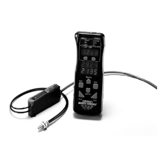
- Page 2 E3X-DA-N (Digital display not lit) This ECO label is indicated on products that meet the environmental standards established by OMRON. Beeper-sized, new-generation Mobile Console unleashing the power of the ultimate fiber amplifier Remote setting/adjustment function Simultaneous turning possible using group teaching.
-
Page 3: Ordering Information
Infrared models E3X-DAH6 E3X-DAH8 Slave E3X-CN12 Master E3X-CN11 Differential output type E3X-DA6D Slave E3X-CN12 ON/OFF output Water-resistant models XS3F-M421-40#-A E3X-DA14V E3X-DA44V (M8 Connector) XS3F-M422-40#-A Master E3X-CN21 Twin-output models E3X-DA6TW E3X-DA8TW Slave E3X-CN22 E3X-DA-N A-421 Downloaded from Elcodis.com electronic components distributor... - Page 4 Amplifier units Connectors (Order Separately) Note: Stickers for Connectors are included as accessories. Item Shape Cable length No. of conductors Model E3X-CN11 Master connector E3X-CN21 E3X-CN12 Slave con- nector E3X-CN22 Sensor I/O Connectors (Order separately) Size Cable type Shape Cable length Model XS3F-M421-402-A Straight...
- Page 5 Operating: Groups of 1 to 3 amplifiers: -25 to +55°C, Groups of 4 to 11 amplifiers: -25 to +50°C, Groups of Ambient temperature 12 to 16 amplifiers: -25 to +45°C Storage: -30 to +70°C (with no icing and condensation) Ambient humidity Operating/Storage: 35% to 85% RH (with no condensation) E3X-DA-N A-423 Downloaded from Elcodis.com electronic components distributor...
- Page 6 Standard Monitor-out- Infrared Water-resis- Twin-output Type Mark-detecting models models put models models tant models models Model E3X-DA11-N E3X-DA21-N E3X-DAB11-N E3X-DAG11-N E3X-DAH11-N E3X-DA11V E3X-DA11TW output E3X-DA41-N E3X-DA51-N E3X-DAB41-N E3X-DAG41-N E3X-DAH41-N E3X-DA41V E3X-DA41TW Item output Insulation resistance 20 M min. at 500 VDC Dielectric strength 1,000 VAC at 50/60 Hz for 1 minute Vibration resistance...
- Page 7 *2. Value applied when the response time is set to 3-11. The value can be detected if the temperature varies within the operating ambient temperature. (Value when the sensing object is operating) *3. The digital value is 1000 and the value can be detected in each detection area. Refer to the E3X-DA-N for the note of the fiber unit. (Reflective model) Sensing distance (mm)*1...
- Page 8 Differences from E3X-DA-N amplifier unit Differential output type (edge detection type) Item Prewiring type amplifier units with Connectors Item NPN output E3X-DA11D E3X-DA6D Power consumption Power consumption 960 mW max. (at power supply voltage 24 V, power consumption 40 mA max.)
-
Page 9: Output Circuit Diagram
Note: With E3X-DA#TW models, only channel 1 is output when set for area sensing operation. L ON The range between the CH1 and CH2 thresholds turns ON D ON The range between the CH1 and CH2 thresholds turns OFF (CH2 is always OFF) E3X-DA-N A-427 Downloaded from Elcodis.com... - Page 10 PNP output Output transis- Mode selection Model Timing chart Output circuit tor Status switch Incident light No incident light Operation Indicator (orange) Brown Operation Indicator L ON Display Light ON (orange) E3X-DA41-N (LIGHT ON) Output E3X-DAB41-N transistor Control output Main Black 12 to 24 E3X-DAG41-N...
- Page 11 2. For details about the K3NX, refer to the K3NX Datasheet 0 V Blue (N084) or the K3NX Operation Manual (N90). 3. This wiring is for the K3NX, with DC power supply E3X-DA-N 12 to 24 specifications and the Monitor (Analog) Sensor with DC power supply specifications. Check respective power supply specifications before wiring them.
-
Page 12: Operation
Operation General Changing the Display (RUN Mode) Zero-reset (RUN Mode) Set the mode selector Digital incident level (4000 max.) Digital incident level (4000 max.) Set the mode selector (Factory-set to RUN) TEACH MODE To reset to zero again: TEACH Digital Percent To return the initial digital incident level: TEACH MODE... - Page 13 Alternates MODE Display orientation Reversing display setting TEACH Standard (factory-set) Alternates TEACH TEACH Reverse Note: It is not possible to set an lower limit TEACH that is lower than the upper limit. E3X-DA-N A-431 Downloaded from Elcodis.com electronic components distributor...
- Page 14 Twin-output models Setting Functions in SET Mode Set the mode selector There are four different sensitivity settings. TEACH Digital incident level display Setting the Changing the operating mode operating mode The operating mode for the channel set MODE with the channel-selection switch can be Timer function Displayed as "t".
- Page 15 Then they return to the digital in- There is no operation mode selector for twin-output models. (green) cident level display. (Red indica- tors start flashing if setting is not OK.) Set to RUN mode. E3X-DA-N A-433 Downloaded from Elcodis.com electronic components distributor...
- Page 16 Precautions Correct Use Amplifier units Design Adjustment Power ON Mutual interference prevention function The sensor is ready to sense an object within 200 ms after turn- The digital display value may vary due to the light from the ing the power ON. If the load and sensor are connected to differ- other sensor.
- Page 17 When fitting the Mobile Console, set the end plate in the guide as shown in the following figure. End Plate Tensile stress for connectors (including cables) E3X-CN11, E3X-CN21, E3X-CN22: 30 N max. E3X-CN12: 12N max. E3X-DA-N A-435 Downloaded from Elcodis.com electronic components distributor...
-
Page 18: Dimensions (Unit: Mm)
Dimensions (Unit: mm) Amplifier Units prewired With Mounting Blanket Attached E3X-DA11-N E3X-DAG11-N E3X-DA21-N 44.9 x 3 = 14.7 Incident level display E3X-DAH11-N E3X-DAB11-N E3X-DAB41-N 17.15 Threshold level display 13.05 E3X-DA41-N E3X-DAG41-N E3X-DA51-N (A) * 1 E3X-DAH41-N E3X-DA11D Operation Indicator 64.3 Two, 38.6 2.4 dia. - Page 19 Dimensions with Slave Connector Connected 67.5 67.5 64.3 64.3 E3X-CN11: 4.0 dia. E3X-CN12: 2.6 dia. E3X-CN21: E3X-CN22: 4.0 dia. 4.0 dia. 31.5 31.5 17.45 12.95 12.95 11.55 1.8 5.1 3.9 1.8 5.1 3.9 E3X-DA-N A-437 Downloaded from Elcodis.com electronic components distributor...
- Page 20 Amplifier Units M8 Connectors, With Mounting Bracket Attached Water-resistant Models 4.9 x 3 = 14.7 30.05 E3X-DA14V Incident level display * The Mounting Bracket can 25.95 Threshold level display E3X-DA44V also be on side A. Operation Indicator (A) * 1 81.5 Two, 2.4 dia.
- Page 21 12.3 28.8 Channel buttons 17.3 24.3 27.7 Teaching 30.3 button Escape button Optical Enter communications position button 31.2 Power M5 ball 36.7 Mode supply button plunger 51.3 button Function button Battery indicators E3X-DA-N A-439 Downloaded from Elcodis.com electronic components distributor...
-
Page 22: Warranty
Warranty and Limitations of Liability WARRANTY OMRON's exclusive warranty is that the products are free from defects in materials and workmanship for a period of one year (or other period if specified) from date of sale by OMRON. OMRON MAKES NO WARRANTY OR REPRESENTATION, EXPRESS OR IMPLIED, REGARDING NON-INFRINGEMENT, MERCHANTABILITY, OR FITNESS FOR PARTICULAR PURPOSE OF THE PRODUCTS.
Need help?
Do you have a question about the E3X-DA-N and is the answer not in the manual?
Questions and answers