
Subscribe to Our Youtube Channel
Related Manuals for Numark CD MIX-3


Summary of Contents for Numark CD MIX-3
-
Page 1: Table Of Contents
SERVICE MANUAL CD MIX-3 MODEL NO.:CD MIX-3 Contents Caution Specification Block Diagram Packing View Packing View Part List Point To Point Wiring Diagram Exploded View 11-13 Exploded View Part List 14-27 Electrical Part List 28-38 Schematic Diagram 39-47 Printed Circuit Board Diagram... -
Page 2: Caution
Caution Do not forcibly close the CD door when the power is off. 2: To prevent destroying the anti-static protection for the mechanism, please kindly be noted of the following important instruction for installing/disassembling the mechanism: a. When disassembling the mechanism, please make sure to turn off power and short the Anti-static protection welding point before removing the FFC cable. - Page 3 Caution 3: 3-1. Please be aware of wearing an anti-static ring before repairing 3-2. It is forbiddance to adjust the laser pick up VR. 3-3.To protect the mechanism; always short the Anti-static protection welding point before removing the mechanism.
-
Page 4: Specification
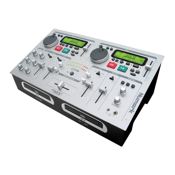
General Specification 1. APPLICATION Model CD MIX-3, Twin front loading CD/MP3 player with mixer. 2. POWER SOURCE DC 12V, 3.0A 3. DIMENSIONS 445(W) x258(D) x156(H) 4. WEIGHT 5.5Kgs 5. FEATURES (1) Electronic Anti-shock CD player System. (2) Seamless Loop play. - Page 5 General Specification 8-5 FREQUENCY RESPONSE: CD/LINE 20-20KHz +1, -1.5dB TCD-782 (Track 3,7) PHONO 20-20KHz +2, -2.5dB/RIAA 20-20KHz +1, /-3dB 8-6 OUTPUT NOISE (W/ 20KHz LPF AND IEC-A WEIGHTED) LINE LESS THEN –75dB PHONO LESS THEN –60dB LESS THEN –55dB 8-7 CD S/N RATIO MORE THAN 80dB TCD-782 (Track 8) NOTE:CD 0dB OUTPUT, MASTER IS SET TO 0dBV OUTPUT.
- Page 6 General Specification 11. ENVIRONMENTAL CONDITION (1) Operating Temperature 5 to 35 deg. C (2) Humidity 25 to 85% RH (non-condensing) (3) Storage Temperature -20 to 60 deg. C 12. ACCESSORIES (1) Operating Instruction 1 pc (2) AC to DC power adaptor 1 pc 13.
-
Page 7: Block Diagram
Block Diagram... -
Page 8: Packing View
Packing View... -
Page 9: Packing View Part List
Packing View Part List REF NO. DESCRIPTION PART NO. Q'TY REMARK POLYFAOM L 506-CDMIX1-223LA POLYFAOM R 506-CDMIX1-223RB SOFT BAG 509-CDMIX1-107 411-X1G-478 American SWITCHING TRANSFORMER(100~240V/50-60HZ,DC12V/3000mA,UL TYPE) 411-X1G-479 Europe SWITCHING TRANSFORMER(100~240V/50-60HZ,DC12V/3000mA,VDE TYPE) 411-X1G-480 United kingdom SWITCHING TRANSFORMER(230V/50HZ,DC9V/200mA,BS TYPE) 411-MX3-488 Australia SWITCHING TRANSFORMER(AC100~240V,47~63Hz,+12V,-+,∮5.5*2.5,SAA TYPE) 411-MX3-489 Korea SWITCHING TRANSFORMER(AC100~240V,47~63Hz,+12V,-+,∮5.5*2.5,K TYPE) -
Page 10: Point To Point Wiring Diagram
Point to Point Wiring Diagram CN05A CONTROL PCB CN315 BALANCE OUTPUT PCB LEVER METER PCB W204 W315 CN302 TO MIX PCB CN309 TO MIX PCB W304 CN310 CN306 MIXER PCB CROSS FADER PCB CN314 HEADPHONE PCB CN507 CN09 CN107 CN05 W105 BUFFER PCB BUFFER PCB... -
Page 11: Exploded View
Exploded View... -
Page 12: Exploded View Part List
Exploded View Part List REF NO. DESCRIPTION PART NO. Q'TY REMARK FRONT CHASSIS ASS'Y 703-CDMIX2-533 MECHA ASS'Y 704-HDJ201-162 BALANCE OUTPUT PCB ASS'Y 704-KMX01-5873 CROSS FADER PCB ASS'Y 704-CDMIX1-2283 SW PCB ASS'Y 704-CDMIX2-3179 HEADPHONE PCB ASS'Y 704-CDMIX2-3180 MIC PCB ASS'Y 704-CDMIX2-3181 LEVER METER PCB ASS'Y 704-MX3-7813 SERVO PCB ASS'Y... - Page 13 Exploded View Part List REF NO. DESCRIPTION PART NO. Q'TY REMARK CERAMIC CAPACITOR(0.01uF/50V,Z,TAPING 6,Z5V) 413-3113-028 TRANSISTOR(2SB1274) 416-HC1421FR-056 DECORATIVE PLATE 501-MIX3A-1120 FUSE LABEL 501-MIX1NS-1298 American, Japan Europe,United FUSE LABEL(46*6mm,t=0.08mm) 501-CDMIX1-1298A kingdom,Australia,Kore a, Argentina 504-SPANDMK2-156 SPACER SUPPORT(H-17,WHITE,H=17.1,∮5.5) NUT(M3*P0.5) 601-A100-004 CD SPRING 603-PRODJ2-224A KNOB ( SILICA GEL 7PCS ) 604-MIX3A-126A KNOB ( SILICA GEL 3PCS )
- Page 14 Exploded View Part List REF NO. DESCRIPTION PART NO. Q'TY REMARK 406-CDMIX1-486 GROUND WIRE(L=100mm,AWM1007 AWG24.BLACK) GROUNDING SHIELD 300-F202-001 1P LEAD WIRE(L=60mm,AWM1007,AWG28,TS,BLACK) 406-CDMIX2-701 LEFT MECHA 404-DJ1-906 5P CONNECTOR WIRE(L=230mm,AWM1007 AWG26,P=2mm) CN103,RIGHT MECHA TO CN503 LEFT MECHA 6P CONNECTOR WIRE 404-CDMIX2-1717 CN102,RIGHT MECHA TO CN502 LEFT MECHA...
-
Page 15: Electrical Part List
Servo PCB Ass'y Part List REF NO. DESCRIPTION PART NO. Q'TY REMARK SERVO PCB ASS'Y 704-MX3-8248 FIXED (SECC 1.2t) 300-9700-1246 CN103,CN503 5P SOCKET(CKM2001WV-5P 180°WHITE) 404-1210S-094A CN102,CN502 6P SOCKET(CKM2001WV-6P 180°WHITE) 404-3113-052A CN04 26P FFC CONNECTOR 404-CDMIX2-1153 CN07A 9P SOCKET(CKM2001WV-9P 180°WHITE) 404-CDMIX2-1200A CN104,CN504 404-CDN22A-679 12P SERIES FEMALE PCB CONNECTOR(H=8.42mm,180DEGREE... - Page 16 Servo PCB Ass'y Part List REF NO. DESCRIPTION PART NO. Q'TY REMARK R111,R511 CHIP RESISTOR(33K OHM,1/8W,0805,J,TP 150V) 412-DV330-318 R135,R136,R137,R536,R5 CHIP RESISTOR(47K OHM,1/8W,0805,J,TP 150V) 412-DV330-321 37,R130,R530,R535 CHIP RESISTOR(12K OHM,1/8W, 0805,J,TP,150V) 412-DV330-330 R101,R102,R501,R502 CHIP RESISTOR(15K OHM,1/8W,0805,J,TP 150V) 412-DV330-331 R113,R114,R129,R529 R584,R123,R125,R126,R1 73,R174,R175,R176,R184, CHIP RESISTOR( 220 OHM,1/8W,0805,J,TP 150V ) 412-DV330-333 R198,R573,R574,R575,R5 76,R598...
- Page 17 Servo PCB Ass'y Part List REF NO. DESCRIPTION PART NO. Q'TY REMARK CERAMIC CAPACITOR(0.1uF/50V,Z,TAPING,Y5V) 413-3113-035 C143,C505,C131,C506,C511 C101,C102,C104,C108,C1 09,C126,C130,C146,C179, 413-3113-046 ELEC. CAPACITOR(100uF/10V,M,105℃,TAPING 5*11)(Cd,Pb,Hg,Cr) C501,C502,C504,C508,C5 09,C526,C530,C546,C579 C140,C540,C161,C165,C1 ELEC. CAPACTIOR(10uF/25V,M,105℃,TAPING 5*11) 413-3113-052 66,C181,C182,C561,C565, C566,C581,C582 C162,C562 413-HT8015-169 ELEC. CAPACITOR(470uF/10V,M, 105℃,TAPING 8*12)(Cd,Pb,Hg,Cr) 413-KC220-119 C135,C137,C535,C537 ELEC. CAPACITOR(220uF/10V,M,105℃,TAPING 6.3*11)(Cd,Pb,Hg,Cr C132 CERAMIC CAPACITOR(3300pF/50V,K,TAPING,Y5P) 413-KMD510-151 C120...
- Page 18 Control PCB Ass'y Part List REF NO. DESCRIPTION PART NO. Q'TY REMARK CONTROL PCB ASS'Y 704-MX3-5628 TONEARM TUBE 300-CD3000-474A JOG201,JOG202 SRGP SW(SRGPHJ-A-3-1,8PIN) 403-HDJ7000-086 W506 3P 2.5CONNECTOR WIRE(L=340mm,AWM2468,AWG26) 404-MX3-2216 W106 3P 2.5CONNECTOR WIRE(L=270mm,AWM2468,AWG26) 404-MX3-2217 CN05A 404-MX3-2940 4P 2.5 CONNECTOR WIRE(L=220mm,AWM2468,AWG26,BLACK/WHITE) CN204 404-MX3-2941 4P 2.5 CONNECTOR WIRE(L=80mm,UL2547/1007,#28*2C/26,GRAY/RED) D210,D208,D206,D216,D2...
- Page 19 Control PCB Ass'y Part List REF NO. DESCRIPTION PART NO. Q'TY REMARK C222,C204,C205,C209,C2 CHIP CAPACITOR(0.1uF/ 50V,Z,0805 TYPE,Y5V) 413-DV330-313 08,C213,C212,C214 C207,C206 CHIP CAPACITOR(20pF/ 50V,J,0805 TYPE,NPO) 413-DV330-315 Q201,Q202 TRANSISTOR(DTC124EKAT146/DTC124EKA) 416-CDN88-044 Q203,Q204 TRANSISTOR(2SA1037AKT146R/2SA1037AKR) 416-CDN88-045 IC201 IC(HD6413008F25V,FP-100B) 417-DJ5500-578 IC203,IC204 IC(ST7066-0B-QG,QFP-80) 417-MX3-743 SW201,SW202,SW203,S W204,SW205,SW206,SW2 07,SW208,SW209,SW210, SW211,SW212,SW213,S TACT SW(H=5mm,TAPING) 403-DCM270X-101A...
- Page 20 Mixer PCB Ass'y Part List REF NO. DESCRIPTION PART NO. Q'TY REMARK MIXER PCB ASS'Y 704-MX3-7818 LEVER SW(LBC22B-20K,6PIN) 403-CDMIX1-114 SW303,SW304,SW305,SW307 PUSH SW(SPEA12MC06-HF) 403-QMX1-056 SW308,SW309,SW310 W304 TO F/B 404-CDMIX1-958 5P 2.0-2.5RIBBON WIRE(L=100mm,AWM2468 AWG26*5C) MIXER/B W315 404-CDMIX1-960 6P CONNECTOR WIRE(L=220mm,AWM2547 AWG28*2C,P=2.5mm)(Cd,Pb) CN309 4P SERIES FEMALE PCB CONNECTORS 404-CDMIX1-971 CN302...
- Page 21 Mixer PCB Ass'y Part List REF NO. DESCRIPTION PART NO. Q'TY REMARK C357,C375,C376,C523,C5 ELEC. CAPACITOR(22uF/25V,M,105℃,TAPING 5*11) 413-DV330-332 24,C545,C387,C358,C388, C546 CERAMIC CAPACITOR(22pF/50V,J,TAPING,NPO) 413-HP1010K-199 C333,C334,C356,C519,C355,C520 POLYESTER CAPACITOR(0.0015uF/50V,J,TAPING) 413-HT7016-219 C549,C550,C551,C552 C368,C399,C374,C338,C3 CERAMIC CAPACITOR(47pF/50V,J,TAPING,NPO) 413-HT8015-153 73,C400 C556,C555 CERAMIC CAPACITOR(150pF/50V,J,TAPING,SL) 413-HT8015-154 CERAMIC CAPACITOR(330pF/50V,K,TAPING,Y5P) 413-KC220-116 C504,C528,C503,C527 C391,C393 POLYESTER CAPACITOR(0.047uF/50V,J,TAPING) 413-KT300-099...
- Page 22 Mixer PCB Ass'y Part List REF NO. DESCRIPTION PART NO. Q'TY REMARK R417,R416 CARBON FILM RESISTOR(680 OHM,1/6W,J,T-26) 412-3113-070 CARBON FILM RESISTOR(1.8K OHM,1/6W,J,T-26) 412-3113-075 R506,R534,R505,R533 CARBON FILM RESISTOR(1K OHM,1/6W,J,T-26) 412-3113-078 R439,R373,R391,R440,R374 R395,R396 CARBON FILM RESISTOR(36K OHM,1/6W,J,T-26) 412-HV3363K-351 CARBON FILM RESISTOR(47 OHM,1/6W,J,T-26) 412-KC220-133 R556,R527,R555,R431,R432,R528 R365...
- Page 23 Power PCB Ass'y Part List REF NO. DESCRIPTION PART NO. Q'TY REMARK POWER PCB ASS'Y 704-MX3-5936 American, Japan Europe,United POWER PCB ASS'Y 704-MX3-5866 kingdom,Australia ,Korea, Argentina P/B CN312 TO 404-CDMIX2-1197 4P CONNECTOR WIRE(L=190mm,AWM2877 AWG26,P=2.5mm) P/B CN307 TO 404-CDMIX2-1210 5P CONNECTOR WIRE(L=190mm,AWM2877 AWG26,P=2.5mm) P/B CN311 TO 404-CDMIX2-1305 4P CONNECTOR WIRE(L=140mm,AWM2877 AWG26,P=2.5mm)
- Page 24 Power PCB Ass'y Part List REF NO. DESCRIPTION PART NO. Q'TY REMARK R439 CARBON FILM RESISTOR(0.22 OHM,1/4W,J,T-52) 412-KM501-292 D302 ZENER DIODE(MTZJ13-A,1/2W,T-77) 414-BJ1900-014 D333 DIODE(RB441Q-40,0.1A/40V,T-77) 414-CDMIX1-104 HEAT SINK & TRANSISTOR ASS'Y 704-MX3-5867 IC311 IC(BA05T,3PIN) 417-CDN34A-314 HEAT SINK(100*49.5mm,W11-162) 425-CDMIX2-048 SCREW(3*8mm TTB) 602-2002-077...
- Page 25 Balance Output & Sw & Mic PCB Ass'y Part List REF NO. DESCRIPTION PART NO. Q'TY REMARK BALANCE OUTPUT PCB ASS'Y 704-KMX01-5873 CN315 6P SOCKET(CKM2501WR-6P 90°BLUE) 404-HV3500K-625A C408 ELEC. CAPACTIOR(10uF/25V,M,105℃,TAPING 5*11) 413-3113-052 L405,L406 CHOKE COIL(14*6mm,100MHZ,750ohm) 415-205-279 IC309 IC(BA15218N,SIP8) 417-KT300-026 RCH,LCH BALANCE JACK(JY-5030-030G)(Pb,Cd) 420-CDMIX1-083 CHIP CAPACITOR(1000pF/50V,J,0805 TYPE,NPO)
- Page 26 Buffer PCB Ass'y Part List REF NO. DESCRIPTION PART NO. Q'TY REMARK BUFFER PCB ASS'Y 704-MX3-5627 CN05 3P SOCKET(CKM2501WV-3P.180°WHTIE) 404-HV3500K-623A CN01 8P2.5 SOCKET(CKM2501-WV-8P,WHITE) 404-RCC1055-1569A R04,R10,R12,R16 CARBON FILM RESISTOR(220 OHM,1/6W,J,T-26) 412-3113-058 RB01 412-DJ1-420 THICK FILM RESISTOR NETWORKS(10K OHM,1/8W J,RA TYPE,7R8P) CERAMIC CAPACITOR(0.1uF/50V,Z,TAPING,Y5V) 413-3113-035 C26,C28 413-KC220-119...
- Page 27 Output PCB Ass'y Part List REF NO. DESCRIPTION PART NO. Q'TY REMARK OUTPUT PCB ASS'Y 704-MX3-5865 CN301A TO S/B 404-CDMIX2-1198 9P CONNECOT WIRE(L=230mm,AWM2468 AWG26*5C/4C) CN301B TO S/B 404-CDMIX2-1205 8P CONNECTOR WIRE(L=250mm,AWM2468 AWG26*4C) W11 TO S/B CN11 404-CDMIX2-1206 4P CONNECTOR WIRE(L=140mm,AWM1007 AWG26)(Cd,Pb) W12 TO S/B CN12 404-CDMIX2-1207 4P CONNECTOR WIRE(L=140mm,AWM1007 AWG26)(Pb,Cd)
- Page 28 Cross Fader & Headphone & Lever Meter PCB Ass'y Part List REF NO. DESCRIPTION PART NO. Q'TY REMARK CROSS FADER PCB ASS' Y 704-CDMIX1-2283 CN306 5P SOCKET(CKM2501WR-5P 90°WHITE) 404-SPPW3-513A VR PCB(94V0,164*108*1.6t) 405-CDMIX1-510 VR304 SLIDE VR(100KB*2,RF45E12G3502-HF) 418-CDMIX1-063 HEADPHONE PCB ASS' Y 704-CDMIX2-3180 CN314 TO MIX/B 404-XDM250-1279...
-
Page 29: Schematic Diagram
Schematic Diagram... - Page 30 Schematic Diagram...
- Page 31 Schematic Diagram...
- Page 32 Schematic Diagram C311 R313 +12V 100/16 405-CDMIX2-618 R303 IC301A C303 C405 BA15218 C309 JK301D CN11 180P C301 R301 100P -12V 10/25 SW301 R314 100P LINE2/PH R305 R307 R309 270K C347 47/16 C415 AUX2 C312 C305 C307 100/16 0.01 0.01 0.0033 L301 R304 IC301B...
- Page 33 Schematic Diagram JK304 R444 R443 HEADPHONE 6.4 DIA. AGND L315 R446 CN314 BEAD C557 JK305 1000P L316 R445 AGND HEADPHONE 3.5 DIA. TO MIX PCB AGND BEAD L317 3P,P=2.5 BEAD C558 1000P APPROVED CHECKED DRAWING Title HEADPHONE PCB Size Number Revision 405-CDMIX2-619A Date:...
- Page 34 Schematic Diagram...
- Page 35 Schematic Diagram...
-
Page 40: Printed Circuit Board Diagram
Printed Circuit Board Diagram 405-CDMIX2-623D/619A MIXER/HEADPHONE PCB... - Page 42 405-CDM02-1455A LEVER METER PCB...
- Page 43 Printed Circuit Board Diagram 405-CDMIX2-617B/618/622A OUTPUT/SW/MIC PCB...
- Page 46 Printed Circuit Board Diagram 405-CDMIX1-508C VOLUME PCB...
- Page 47 Printed Circuit Board Diagram 405-CDMIX1-510 VR PCB...
- Page 48 Printed Circuit Board Diagram POWER PCB 405-CDMIX2-752...
- Page 49 IC Block Diagram IC BLOCK DIAGRAM 417-KC720-049 BA6218 MOTOR Control logic...
- Page 50 IC Block Diagram IC(PCM1716E,28PIN,SOP) 417-DCM270X-327A...
- Page 51 IC Block Diagram IC BLOCK DIAGRAM 417-DCM280-596 VA5979S PreV MUTE + − INTER- FACE LEVEL SHIFT THERMAL Vref SHUTDOWN INTER- FACE REGULATOR T. S. D MONITOR INTER- FACE 抵抗値の単位は〔Ω〕...
- Page 52 IC Block Diagram IC BLOCK DIAGRAM 417-DJ5500-578 MAX003 Port 3 Port 4 Address bus Data bus (upper) Data bus (lower) EXTAL XTAL STBY H8/300H CPU RESO φ/P6 Interrupt controller LWR/P6 BACK/P6 BREQ/P6 WAIT/P6 Watchdog timer ADTRG/CS /IRQ (WDT) /IRQ 16-bit timer unit /IRQ Serial communication interface...
- Page 53 IC Block Diagram 20. 417-HDJ2450-693C IC(SM8952AC25J PLCC-44)
- Page 54 IC Block Diagram IC BLOCK DIAGRAM 417-HDJ2000-413D IC(AT29C010A-90JU,PLCC-32)
- Page 55 IC Block Diagram 417-HMD5000-282 BAOOT / BAOOFP series Regulator ICs Low saturation voltage type 3-pin regulator BAOOT / BAOOFP series The BAΟΟT and BAΟΟFP series are fixed positive output low drop-out type, 3-pin voltage regulators with positive output. These regulators are used to provide a stabilized output voltage from a fluctuating DC input voltage. There are 10 fixed output voltages, as follows:3V, 3.3V, 5V, 6V*, 7V, 8V, 9V, 10V, 12V and 15V.
- Page 56 IC Block Diagram 18. 417-MCDS4-735 IC(M29W800B70N6.SMD)
- Page 57 417-MCDS4-736 IC(SCF5249LPV120.SMD)
- Page 58 IC Block Diagram 16. 417-MCDS4-738 IC(XC9536XL-10VQ44C,SMD) 17. 417-MCDS4-737 IC(BA18BCOFP-E2,SMD) BA18BCO...
- Page 59 IC Block Diagram ST7066 Block Diagram 417-MX3-743 OSC1 OSC2 Reset Circuit Timing Generator Instruction COM1 to Register (IR) COM16 Display 16-bit Common data RAM shift Signal Interface (DDRAM) registe Driver 80x8 bits Instruction Decoder SEG1 to SEG40 40-bit 40-bit Segment shift latch Signal...
- Page 60 IC Block Diagram Audio ICs BA6820F / BA6822S / BA6822F 417-SA12-491 FBlock diagram FAbsolute maximum ratings (BA6820F / BA6822F) (Ta = 25_C) (BA6822S) (Ta = 25_C) FRecommended operating conditions (Ta = 25_C)
- Page 61 IC Block Diagram 417-Q2221-180...
- Page 62 IC Block Diagram 417-CDN34A-314...
- Page 63 IC Block Diagram BAOOT / BAOOFP series 417-CTB200-500 Regulator ICs Low saturation voltage type 3-pin regulator BAOOT / BAOOFP series The BAΟΟT and BAΟΟFP series are fixed positive output low drop-out type, 3-pin voltage regulators with positive output. These regulators are used to provide a stabilized output voltage from a fluctuating DC input voltage. There are 10 fixed output voltages, as follows:3V, 3.3V, 5V, 6V*, 7V, 8V, 9V, 10V, 12V and 15V.
- Page 64 IC Block Diagram IC BLOCK DIAGRAM 417-CDMIX1-388 NJM2360...
-
Page 65: Ic Block Diagram
IC Block Diagram IC BLOCK DIAGRAM 417-DCM280-588 CXA-2581N RFAC EQ_ON/OFF RW/ROM DC_OFST RFDCI RFDCO RW/ROM VOFST RW/ROM TE_BAL RW/ROM VOFST RW/ROM VOFST RW/ROM RW/ROM APC-OFF (Hi-Z) RW/ROM VOFST (H/L) - Page 66 IC Block Diagram IC BLOCK DIAGRAM 417-DCM280-587 CXD3068Q 11 13 68 65 66 71 72 59 60 TES1 TEST FSTO Clock Error XRST Generator Corrector demodurator RFAC Interface ASYI Asymmetry ASYO Corrector ASYE Digital BIAS DOUT XPCK Sub Code FILO Processor Digital FILI...
- Page 67 IC Block Diagram 417-KT300-026 BA15218 B15218 OUT1 – IN1 OUT2 – – – + IN1 – – IN2 + IN2...
- Page 68 Trouble Shotting SYMPTOM POSSIBLE CAUSE CORRECTIVE ACTIN The power fails to switch on when the Poor power plug connection at the AC Insert the power plug firmly into the POWER switch is set to on outlet AC outlet Disc play does not start The disc is loaded upside down Reload the disc with the label with the The disc is too dirty...
Need help?
Do you have a question about the CD MIX-3 and is the answer not in the manual?
Questions and answers