
Subscribe to Our Youtube Channel
Related Manuals for Carat P-7010


Summary of Contents for Carat P-7010
- Page 1 Gebruiksaanwijzing Zaagmachine voor bouwmaterialen Mode d’emploi Scie surtable de chantier Operating Instructions Masonry saws P-7010...
- Page 5 Art. 90169 - Laser...
- Page 8 IN EEN OMGEVING MET EXPLOSIEGEVAAR Deze handleiding is een integraal onderdeel van de machine. Deze handleiding werd verwezenlijkt door CARAT CENTRAL BV om de benodigde LET OP! informatie te verschaff en aan degenen die bevoegd zijn te handelen op het apparaat gedurende de GEBRUIK TE ALLEN TIJDE PERSOONLIJKE verwachte levensduur.
- Page 9 Ø int. Controleer het apparaat op beschadigingen. N° Controleer voor gebruik van het apparaat Made by: CARAT NEDERLAND BV of de veiligheidsinrichtingen effi ciënt zijn en Nikkelstraat 18, 4823 AB Breda (NL) goed functioneren en of er delen beschadigd zijn. Controleer of de bewegende delen goed...
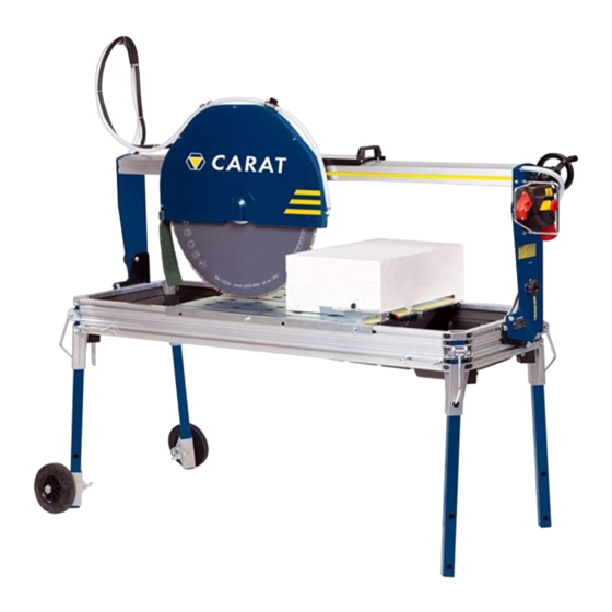
- Page 10 Startcondensator Waterpeil 4. Beschrijving van de machine opvangbak Het mes Bouw P-7010 is een specifi eke machine voor het snijden van banen van baksteen, E i n d s c h a k e l a a r natuursteen, graniet,...
- Page 11 P-7010 Max. diameter werktuig 700 mm Opening werktuig: 25,4 mm Max. snijdiepte: 275 mm Maximale snijlengte 615 mm 795 mm** Pomp voor watercirculatie: S3 230V 50/60Hz Afmetingen machine: P-7010 760 x 1950 x h. 1775 mm geluid door deze machine...
- Page 12 TRANSPORT (motorzijde) b) til de poot op en voer het ondersteuningswiel erin De P-7010 kan met behulp van de handgrepen (foto 4); gemakkelijk worden vervoerd. c) vergrendel de poot met het overeenkomstige vergrendelingsmiddel; Controleer voordat u de machine verplaatst of:...
- Page 13 BEGIN VERPLAATSEN ZOALS WEES ER VOOR EEN CORRECTE PLAATSING AANGEDUID OP FOTO 6 VAN DE MACHINE ZEKER VAN DAT HET BOVENSTE GAT VAN DE POOT OVEREENKOMT MET DIE VAN DE POOTVERBINDING, VOORDAT ER WORDT OVERGEGAAN DE DEFINITIEVE VERGRENDELING (FOTO 8). c) vergrendel de poten één voor één (foto 8);...
- Page 14 f) Met behulp van een 6 mm inbussleutel, verwijder l) Met de 5 mm inbussleutel om de tram stoppen de schroef mes deksel (Foto 10). start snijden in positie A, zoals aangegeven in g) Draai het disc-deksel en vergrendel het zelfde foto 13.
- Page 15 LET OP! CONTROLES VOORAF NAAST DE KNOPPEN HERINTEREN ALTIJD DE LET OP! SLUITMOER OP DE SCHIJFKAP DE P-7010 IS ONTWORPEN OM UITSLUITEND MET WATER TE WERKEN. LET OP! DE SCHROEFDRAAD VAN DE BORGMOER VAN HET BLAD IS LINKSDRAAIEND. • Houd, bij het monteren van het blad, rekening met de draairichting, die duidelijk staat vermeld op het gereedschap.
- Page 16 DIENT DE BEDIENER TE CONTROLEREN OF ER TENMINSTE 150 CM VRIJE RUIMTE RONDOM Type P-7010 DE MACHINE AANWEZIG IS (Foto 18). OM OP VEILIGE WIJZE TE KUNNEN WERKEN, 1) In een 5 mm inbussleutel, draai de wagen stopte...
- Page 17 4) Herhaal de procedure op de kar stopte aan het einde van het snijden. LET OP! WIJZIGING VAN DE CUT ZAL MORSEN VAN WATER UIT DE MACHINE. Type P-7010 Voer alleen die activiteiten 1,2 en 3 LET OP! LASERMARKEERDER NIET VERANDER DE POSITIE VAN DE TRAM...
- Page 18 LET OP! DE LASERMARKEERDER IS OPERATIONEEL ZODRA DE MACHINE IS AANGESLOTEN OP HET ELEKTRICITEITSNETWERK. LET OP! DIRECTE BLOOTSTELLING AAN ZONLICHT KAN AFBREUK DOEN AAN DE EFFICIËNTIE VAN DE LASERMARKEERDER. HET IS DAAROM AANGERADEN OM DE MACHINE IN EEN OVERDEKTE RUIMTE TE draai de drie blokkeringsschroeven van het GEBRUIKEN.
- Page 19 Tijdens de vertraging van het snijwerktuig als gevolg van het stoppen van de machine. 11. Overige Risico’s 12. Onderhoud CARAT CENTRAL BV heeft in de ontwerpfase rekening gehouden met de aspecten die kunnen LET OP! leiden tot veiligheidsrisico’s en met de gezondheid van de bedieners.
- Page 20 REINIGEN LET OP! DE MACHINE NIET REINIGEN MET WATER ONDER HOGE DRUK. De P-7010 kan gemakkelijk worden gereinigd door de borgmoeren aan de zijkant los te draaien en het werkvlak te verwijderen. Leeg de machine van verwerkingsresten, met behulp van de stop op de bodem van de tank.
- Page 21 13. De machine ontmantelen Als de machine of delen ervan worden ontmanteld, dienen de afvalmaterialen volgens de wettelijke voorschriften inzake afvalstoffen worden behandeld. Elektrische motor Aluminium Staal Koper Polyamide Hoofdgedeelte Staal Polyamide Aluminium Dompelpomp Polyamide Staal Aluminium Koper Epoxyhars De Europese Richtlijn 2002/96/EG schrijft voor afgedankte elektrische...
- Page 22 14. Defecten en oplossingen LAAT DE STEENZAAGMACHINE T-5010/T-6010 ALLEEN DOOR DESKUNDIGE TECHNICI REPAREREN. Deze machine voldoet aan alle veiligheidsnormen. Alleen ervaren technici mogen reparaties uitvoeren met originele reserveonderdelen. Als u dit niet doet, kunt u de gebruiker van de machine ernstig in gevaar brengen.
- Page 23 CES INSTRUCTIONS • Le fabricant décline toute responsabilité en cas d’emploi de la scie sur table P-7010 avec Maintenez de l’ordre sur votre lieu de travail des outils diff érents de ceux indiqués au Le désordre dans le lieu de travail augmente le paragraphe «...
- Page 24 Ø int. Contrôlez si votre appareil est endommagé Avant d’utiliser de nouveau l’outil, vérifi ez N° soigneusement le parfait fonctionnement des Made by: CARAT NEDERLAND BV dispositifs de sécurité ou l’éventuelle présence Nikkelstraat 18, 4823 AB Breda (NL) pièces endommagées.
- Page 25 Niveau d'eau démarrage dans la cuve de récupération 4. Description de la machine La scie sur table de chantier P-7010 est une Fin de course tête machine conçue pour les travaux de coupe sur moteur des briques, pierres naturelles, granit, ouvrages en béton et semblables, de 275 mm d’épaisseur...
- Page 26 P-7010 Diamètre max. de l’outil: 700 mm Trou outil: 25,4 mm Profondeur maximum de coupe à 90°: 275 mm Longueur maximale de coupe 615 mm 795 mm** Pompe de circulation de l’eau: S3 230V 50/60Hz Dimensions machine: P-7010 760 x 1950 x h. 1775 mm Le niveau de bruit émis par la machine a été...
- Page 27 TRANSPORT b) soulever le pied et l’introduire dans le support roue (photo 4). La P-7010 peut être transportée facilement en c) bloquer le pied avec la fi xation correspondante. utilisant les poignées de transport. d) serrer la vis de blocage du support roue (photo 4).
- Page 28 PROCÉDER DÉPLACEMENT COMME POUR POSITIONNEMENT CORRECT INDIQUÉ SUR LA PHOTO 6. DE LA MACHINE, S’ASSURER, AVANT DE PROCÉDER AU BLOCAGE FINAL, QUE LE TROU SUPÉRIEUR DES PIEDS EST ALIGNÉ SUR LE TROU DE FIXATION CORRESPONDANT (PHOTO 8). c) bloquer les pieds un à la fois (photo 8). POSITIONNEMENT Positionner la machine sur une surface stable.
-
Page 29: Controles Avant L'utilisation
Emboîter le tuyau d’eau sur la vanne de travail (photo 14). sectionnement d’eau (photo 11). i) Insérer la tige serre-tube dans le logement CONTROLES AVANT L’UTILISATION approprié (photo 12). ATTENTION! LA MACHINE P-7010 EST CONÇUE POUR FONCTIONNER EXCLUSIVEMENT AVEC DE L’EAU. - Page 30 Brancher la machine uniquement à un secteur ayant un câble de mise à terre effi cient. En cas de doutes, ne pas brancher la machine. DISPOSITIFS DE COMMANDE ET CONTROLE ATTENTION! La machine P-7010 est équipée d’un cadrant de ATTENTION! commande composé de: PLUS BOUTONS,...
- Page 31 DE COUPE, L’OPERATEUR DOIT VEILLER A LAISSER AU MOINS 150 cm D’ESPACE LIBRE AUTOUR DE LA MACHINE (Photo 18). • P-7010 POUR TRAVAILLER EN TOUTE SECURITE, INTERDIRE AUX AUTRES PERSONNES DE En réglant les dispositifs d’arrêt chariot au début et STATIONNER PRES DE LA MACHINE DURANT à...
- Page 32 Modèle P-7010 ATTENTION! 1) Avec une clé à six pans mâle de 5 mm, desserrer le dispositif d’arrêt chariot au début de la coupe. (Photo 20) NE PAS MODIFIER LA POSITION DU DISPOSITIF D’ARRET CHARIOT A LA FIN DE LA COUPE...
- Page 33 VERS LES YEUX DE L’OPERATEUR. NE PAS FIXER LE FAISCEAU À L’OEIL NU ET TRACEUR LASER NE PAS LE REGARDER DIRECTEMENT AVEC DES INSTRUMENTS OPTIQUES. ATTENTION! APPAREIL LASER EN CLASSE IIIA RÉGLAGE DU TRACEUR L’accessoire traceur laser permet d’eff ectuer plus Si le traceur n’est pas en axe avec la ligne de rapidement les opérations de coupe.
- Page 34 Durant le ralentissement de l’outil de coupe consécutif à l’arrêt de la machine. 12. Entretien 11. Risques résiduels Durant la phase de conception, CARAT CENTRAL ATTENTION! BV a fait particulièrement attention aux aspects susceptibles de provoquer des risques à la sécurité...
- Page 35 Il est possible de nettoyer facilement la P-7010 en arrière (B) (photo 28). desserrant les écrous de blocage et en enlevant la table de travail. Enlever les résidus d’usinage de la machine via le bouchon situé...
- Page 36 13. Élimination En cas d'élimination de toute la machine ou d'une partie de celle-ci, les différents matériaux devront être éliminés conformément à la législation en vigueur. Moteur électrique Corps principal Pompe immergée Résine époxy La Directive Européenne 2002/96/CE dispose que les équipements électriques et électroniques ne soient pas éliminés dans le flux normal des ordures ménagères, mais qu’ils soient collectés séparément,...
- Page 37 14. Recherche des pannes L'OUTIL DOIT ÊTRE RÉPARÉ PAR DU PERSONNEL QUALIFIÉ. Cet outil électrique est conforme aux normes de sécurité correspondantes. Afin d'éviter le risque de créer une situation dangereuse pour l'utilisateur, les réparations ne doivent être effectuées que par du personnel qualifié...
- Page 38 During cutting operations, allow the machine to Keep children away! rest as indicated. Do not let third parties contact tool or extension • P-7010 is not made for use with a continuous cord. All visitors should be kept away from work load. area. •...
- Page 39 Ø int. Stay alert Watch what you are doing. Use common sense. N° Made by: CARAT NEDERLAND BV Do not operate tool when you are inattentive. Nikkelstraat 18, 4823 AB Breda (NL) Check tool for damaged parts Before further use of the tool, check it and the safety devices for damages and be sure that they operate properly.
- Page 40 Starter capacitor Do not wash with water under pressure 4. Machine description The P-7010 site cutter is a machine intended Recovery tank specifi cally for cutting bricks, natural stone, granite, water level concrete items and similar materials, up to a thickness of 275 mm.
- Page 41 P-7010 Max tool diameter: 700 mm Centre hole: 25,4 mm Maximum cutting depth at 90°: 275 mm Maximum cutting length 615 mm 795 mm** Water recirculation pump: S3 230V 50/60Hz Machine dimensions: P-7010 760 x 1950 x h. 1775 mm The noise level of the machine has been measured 6.
- Page 42 (motor side); TRANSPORT b) lift the leg and put it in the wheel support (see picture 4); The P-7010 machine can be easily moved by using c) lock the leg with the relative locking pin; the transport handles. d) tighten...
- Page 43 MOVE THE MACHINE AS INDICATED IN FOR CORRECT MACHINE POSITIONING, MAKE PICTURE 6 SURE THAT THE LEG UPPER HOLE MATCHES THE LEG COUPLING HOLE, BEFORE FINALLY LOCKING IT (SEE PICTURE 8). c) lock the legs one at a time (see picture 8). POSITIONING Place the machine on a stabile surface.
-
Page 44: Checking Before Use
Put the additional splash guard in working position (see picture 14). h) Engage the water hose on the water on-off valve (see picture 11). CHECKING BEFORE USE CAUTION! THE P-7010 MACHINE HAS BEEN DESIGNED i) Insert tube-holder seat FOR WORKING EXCLUSIVELY WITH WATER. (see picture 12). - Page 45 The machine must be connected to an eff ective earth wire. In case of doubt, do not connect the machine. CONTROL DEVICES CAUTION! The P-7010 machine is equipped with a control board made up of: 1) START BUTTON: (BLACK COLOUR) Press the button fully to activate machine starting.
- Page 46 OPERATIONS, THE OPERATOR MUST MAKE SURE THAT AT LEAST 150 cm ARE LEFT FREE Model P-7010 AROUND THE MACHINE (See picture 18). IN ORDER TO WORK IN SAFETY CONDITIONS, 1) With a 5 mm Allen wrench, loosen the cut start...
- Page 47 Position the piece to be cut on the working table stopper. and perform the cutting operation. CAUTION! WHEN THE CUT LENGTH IS MODIFIED, WATER COMES OUT FROM THE MACHINE. Model P-7010 Perform only operations 1, 2 and 3. CAUTION! DO NOT MODIFY THE CUT END CARRIAGE STOPPER POSITION...
- Page 48 position a reference properly on the tool cutting CUTTING WITH LASER MARKER line (see picture 24); connect the machine to the power supply; insert the 5 mm Allen wrench provided position the piece to be cut making sure that the in the hexagonal slot located on the bulb line indicated by the laser marker matches the (see picture 25);...
- Page 49 BEFORE PERFORMING ANY OPERATION OR ADJUSTMENT, DISCONNECT THE MACHINE FROM THE SUPPLY MAINS. During the design phase, CARAT CENTRAL BV paid particular attention to the aspects that may MOTOR CARRIAGE ADJUSTMENT generate risks for the safety and health of operators.
- Page 50 CLEANING CAUTION! DO NOT WASH THE MACHINE WITH HIGH PRESSURE WATER JETS It is extremely easy to clean the P-7010 machine by loosening the locking nuts and dismantling the working table. Through the tap located on the bottom of the recovery tank, remove any working residual from the machine.
-
Page 51: Troubleshooting
Submerged Pump 13. Disposal Polyamide In the event of scrapping the entire machine, it must Steel be disposed of in accordance with the methods laid Aluminium down by current legislation. Copper Electric Motor Epoxy Resin Aluminium W.E.E.E. IT08020000002803 The European Directive 2002/96/CE Steel arranges that in the event of scrapping of Copper... - Page 52 CARAT NEDERLAND BV Nikkelstraat 18, 4823 AB Breda Netherlands www.carat-tools.nl | www.carat-tools.com | www.carat-tools.dk...
Need help?
Do you have a question about the P-7010 and is the answer not in the manual?
Questions and answers