Table of Contents

Subscribe to Our Youtube Channel
Related Manuals for Aim ARINC825

Summary of Contents for Aim ARINC825
- Page 1 Hardware Manual AMC825 - 2/4 ARINC825 Test and Simulation Card Set AIM GmbH Sasbacher Str. 2 79111 Freiburg, Germany Tel: +49-761-45229- 0 Fax: +49-761-45229- 33 sales@aim-online.com www.aim-online.com November 2012 V01.01 Rev. A...
- Page 3 GmbH GmbH AMC825 - 2/4 Hardware Manual ARINC825 Test and Simulation Card Set V01.01 Rev. A November 2012 AIM No: 60-19A1x-16-0101-A...
- Page 4 Notice: The information that is provided in this document is believed to be accurate. No responsibility is assumed by AIM for its use. No license or rights are granted by implication in connection therewith. Specifications are subject to change without notice.
- Page 5 GmbH GmbH DOCUMENT HISTORY Version Cover Date Created by Description V01.00-A 01.02.2011 M. Maier First Release V01.01-A 02.11.2012 M. Maier Removed Chapter 2.2.3 ff.
- Page 6 GmbH GmbH THIS PAGE INTENTIONALLY LEFT BLANK...
-
Page 7: Table Of Contents
Page INTRODUCTION ......................1 ........................1 VERVIEW ................. 2 ANUAL RGANIZED ....................2 PPLICABLE OCUMENTS 1.3.1 P AIM D ................2 RODUCT PECIFIC OCUMENTS HARDWARE INSTALLATION ................3 ..................4 ONNECTING TO THER EVICES 2.1.1 AMC825-2/4 PCB V ....................4 2.1.2 LED... - Page 8 GmbH GmbH THIS PAGE INTENTIONALLY LEFT BLANK...
-
Page 9: Introduction
GmbH INTRODUCTION Overview The AMC825-2/4 is a PMC-CAN interface board with up to 4x CAN and optional ARINC protocol and IRIG-B. 6 LEDs Connectors Krypto Chip Pn1, Pn2 (Option) 4x CAN Interface Bus Master Electrical Isolation FPGA Capability Xilinx Spartan-3E CAN Core Physical PCI Bridge... -
Page 10: How This Manual Is Organized
Section 3 - TECHNICAL DATA - describes the technical specification of the AMC825-2/4 Applicable Documents 1.3.1 Product Specific AIM Documents Reference Manual Application Interface Library Detailed description of the programming interface between the PC and the onboard driver software. AMC825 Hardware Manual... -
Page 11: Hardware Installation
GmbH HARDWARE INSTALLATION Danger! Electric shock risk. Never carry out work while power supply voltage is switched Attention ! Electrostatic discharges may cause damage to electronic components. To avoid this, please perform the following steps before you touch the module, in order to discharge the static electricity from your body: Switch off the power of your computer, but leave it connected to the mains until you have discharged yourself. -
Page 12: Connecting To Other Devices
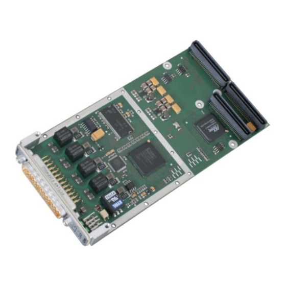
GmbH Connecting to Other Devices 2.1.1 AMC825-2/4 PCB View AMC825 Hardware Manual... -
Page 13: Leds
GmbH 2.1.2 LEDs The AMC825-2/4 is equipped with 6 green LEDs in the front panel. LED Function Indication (LED on) Board (FPGA) booted IRIG-B IRIG-B Link CAN1 Traffic on CAN-Line 1 CAN2 Traffic on CAN-Line 2 CAN3 Traffic on CAN-Line 3 CAN4 Traffic on CAN-Line 4 AMC825 Hardware Manual... -
Page 14: I/O Connector X400 (Dsub25 Male) Pin Assignment
GmbH Connector Assignment 2.2.1 I/O Connector X400 (DSUB25 male) Pin Assignment Signal Signal CAN1_L CAN1_H CAN1_GND CAN2_L CAN2_H CAN2_GND CAN3_L CAN3_H CAN3_GND CAN4_L CAN4_H CAN4_GND IRIG-B_RX+ IRIG-B_RX- IRIG-B_A+ IRIG-B_A- Description of Signals at X400 Name Description This pin is not connected at the module. CANx_L, CANx_H, CAN signals of CAN node x (x= 1, 2, 3, 4). -
Page 15: Pmc Connectors
GmbH 2.2.2 PMC Connectors The module uses the PMC connectors Pn1, Pn2 and Pn4. Pn1 and Pn2 provide the PCI interface and power supply connection. Pn1 and Pn2 are according to PMC specification. Pn4 is not used at this module variant and the pins shall not be connected. AMC825 Hardware Manual... - Page 16 GmbH This page intentionally left blank AMC825 Hardware Manual...
-
Page 17: Technical Data
GmbH TECHNICAL DATA General Technical Data Power supply voltage Nominal voltage: 5 V/DC or 3.3 V/DC, Universal board Current consumption (20 °C): typical: 5 V : 56 mA 3,3V: 570 mA P11 (Pn1): (64-pin PMC connector) - PCI bus Connector P12 (Pn2): (64-pin PMC connector) - PCI bus P14 (Pn4):... -
Page 18: Can Interfaces
GmbH CAN Interfaces Number 4x CAN High-Speed CAN core integrated in FPGA, CAN controller according to ISO11898-1 (CAN 2.0 A/B) Module type AMC-825 physical layer in accordance with ISO11898-2, Physical interface bit rate up to 1 Mbit/s Electrical isolation via dual digital isolators and DC/DC converters has to be set externally Bus termination X400 (DSUB25 male) -
Page 19: Notes
GmbH NOTES Acronyms Analog to Digital Converter AFDX Avionic Full Duplex Switched Ethernet (ARINC 664) ALBI ASP Local Bus Interface Advanced RISC Machine Application Support Processor Bus Interface Processor Bus Interface Unit Controller Area Network Central Processing Unit Cyclical Redundancy Check Digital to Analog Converter.
Need help?
Do you have a question about the ARINC825 and is the answer not in the manual?
Questions and answers