Table of Contents
Advertisement
Quick Links
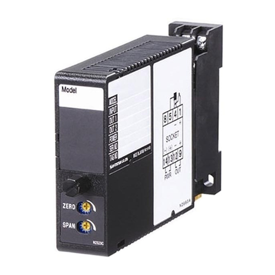
Super-mini Signal Conditioners Mini-M Series
LIMITER
Functions & Features
• Prevents DC output signals from going above or below
preset values
• High and low limits independently adjustable from -10.0 %
to +105 %
• Easy high/low limit setting with the front digital display
• CE marking
• UL approval
Typical Applications
• Protecting the receiving instrument which could
malfunction with an overscale input
• Securing the minimum fuel flow in a combustion control
loop
23 (.91)
76
(2.99)
124
(4.88)
mm (inch)
MODEL: M2LMS–[1][2]–[3][4]
ORDERING INFORMATION
• Code number: M2LMS-[1][2]-[3][4]
Specify a code from below for each [1] through [4].
(e.g. M2LMS-6A-M2/CE/Q)
• Special input and output ranges (For codes Z & 0)
• Specify the specification for option code /Q
(e.g. /C01/S01)
[1] INPUT
Current
A: 4 – 20 mA DC (Input resistance 250 Ω)
A1: 4 – 20 mA DC (Input resistance 50 Ω)
B: 2 – 10 mA DC (Input resistance 500 Ω)
C: 1 – 5 mA DC (Input resistance 1000 Ω)
D: 0 – 20 mA DC (Input resistance 50 Ω)
E: 0 – 16 mA DC (Input resistance 62.5 Ω)
F: 0 – 10 mA DC (Input resistance 100 Ω)
G: 0 – 1 mA DC (Input resistance 1000 Ω)
H: 10 – 50 mA DC (Input resistance 100 Ω)
J: 0 – 10 μA DC (Input resistance 1000 Ω)
SEN TRONIC
AG
Produkte, Support und Service
K: 0 – 100 μA DC (Input resistance 1000 Ω)
GW: -1 – +1 mA DC (Input resistance 1000 Ω)
FW: -10 – +10 mA DC (Input resistance 100 Ω)
Z: Specify current (See INPUT SPECIFICATIONS)
Voltage
1: 0 – 10 mV DC (Input resistance 10 kΩ min.)
15: 0 – 50 mV DC (Input resistance 10 kΩ min.)
16: 0 – 60 mV DC (Input resistance 10 kΩ min.)
2: 0 – 100 mV DC (Input resistance 100 kΩ min.)
3: 0 – 1 V DC (Input resistance 1 MΩ min.)
4: 0 – 10 V DC (Input resistance 1 MΩ min.)
5: 0 – 5 V DC (Input resistance 1 MΩ min.)
6: 1 – 5 V DC (Input resistance 1 MΩ min.)
4W: -10 – +10 V DC (Input resistance 1 MΩ min.)
5W: -5 – +5 V DC (Input resistance 1 MΩ min.)
0: Specify voltage (See INPUT SPECIFICATIONS)
[2] OUTPUT
Current
A: 4 – 20 mA DC (Load resistance 750 Ω max.)
B: 2 – 10 mA DC (Load resistance 1500 Ω max.)
C: 1 – 5 mA DC (Load resistance 3000 Ω max.)
D: 0 – 20 mA DC (Load resistance 750 Ω max.)
E: 0 – 16 mA DC (Load resistance 900 Ω max.)
F: 0 – 10 mA DC (Load resistance 1500 Ω max.)
G: 0 – 1 mA DC (Load resistance 15 kΩ max.)
Z: Specify current (See OUTPUT SPECIFICATIONS)
Voltage
1: 0 – 10 mV DC (Load resistance 10 kΩ min.)
2: 0 – 100 mV DC (Load resistance 100 kΩ min.)
3: 0 – 1 V DC (Load resistance 1000 Ω min.)
4: 0 – 10 V DC (Load resistance 10 kΩ min.)
5: 0 – 5 V DC (Load resistance 5000 Ω min.)
6: 1 – 5 V DC (Load resistance 5000 Ω min.)
4W: -10 – +10 V DC (Load resistance 10 kΩ min.)
5W: -5 – +5 V DC (Load resistance 5000 Ω min.)
0: Specify voltage (See OUTPUT SPECIFICATIONS)
[3] POWER INPUT
AC Power
M2: 100 – 240 V AC (Operational voltage range 85 – 264 V,
47 – 66 Hz)
(90 – 264 V for UL)
DC Power
R: 24 V DC
(Operational voltage range 24 V ±10 %, ripple 10 %p-p max.)
R2: 11 – 27 V DC
(Operational voltage range 11 – 27 V, ripple 10 %p-p max.)
(Select '/N' for 'Standards & Approvals' code.)
P: 110 V DC
(Operational voltage range 85 – 150 V, ripple 10 %p-p max.)
Rugghölzli 2
Tel. +41 (0)56 222 38 18
CH - 5453 Busslingen
Fax +41 (0)56 222 10 12
MODEL: M2LMS
mailbox@sentronic.com
www.sentronic.com
Advertisement
Table of Contents

Related Manuals for M-system Mini-M Series


Summary of Contents for M-system Mini-M Series
- Page 1 MODEL: M2LMS K: 0 – 100 μA DC (Input resistance 1000 Ω) Super-mini Signal Conditioners Mini-M Series GW: -1 – +1 mA DC (Input resistance 1000 Ω) FW: -10 – +10 mA DC (Input resistance 100 Ω) LIMITER Z: Specify current (See INPUT SPECIFICATIONS) Functions &...
-
Page 2: General Specifications
Minimum span: 5 mV Offset: Max. 1.5 times span Load resistance: Output drive 1 mA max.; at ≥ 0.5 V SPECIFICATIONS OF OPTION: Q (multiple selections) COATING (For the detail, refer to M-System's web site.) INSTALLATION /C01: Silicone coating /C02: Polyurethane coating... -
Page 3: Front View
MODEL: M2LMS Groups A, B, C, and D hazardous locations (ANSI/ISA-12.12.01, CAN/CSA-C22.2 No.213) UL/C-UL general safety requirements (UL 61010B-1, CAN/CSA-C22.2 No.1010-1) FRONT VIEW (A) Polarity Indicator LED (B) High/Low Limit Display (C) High/Low Limit Selector Top: High Limit Bottom: Low Limit (D) UP/DOWN Control (E) Zero Adj. - Page 4 MODEL: M2LMS TERMINAL ASSIGNMENTS unit: mm (inch) INPUT RESISTOR (model: REM2) 14 13 Input shunt resistor attached for current input. SCHEMATIC CIRCUITRY & CONNECTION DIAGRAM HI/LO LIMIT UP/DOWN SELECTOR Isolation Low Drift Digital Output Amplifier Computation Driver INPUT OUTPUT – –...
-
Page 5: Component Identification
• Locate the power input rating marked on the product and confirm its operational range as indicated below: Thank you for choosing M-System. Before use, please check 100 – 240V AC rating: 85 – 264V (90 – 264V for UL), contents of the package you received as outlined below. -
Page 6: Maintenance
M2LMS ■ FRONT PANEL CONFIGURATION TERMINAL CONNECTIONS Connect the unit as in the diagram below or refer to the con- (A) Polarity Indicator LED nection diagram on the side of the unit. (B) High/Low Limit Display When an input resistor is provided with the module, attach it together with input wiring to the input screw terminals. -
Page 7: External Dimensions
M2LMS EXTERNAL DIMENSIONS unit: mm (inch) 6 (.23) DIN RAIL 35mm wide 2–4.2x5 (.17x.20) MTG HOLE 6 (.24) deep 8–M3 SCREW 14 13 21.5 (.85) 7.3 (.29) 86.7 (3.41) 15 (.59) 116.7 (4.59) [4 (.16)] 23 (.91) • When mounting, no extra space is needed between units. ■...
Need help?
Do you have a question about the Mini-M Series and is the answer not in the manual?
Questions and answers