Table of Contents
Advertisement
Quick Links
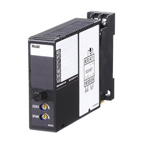
Super-mini Signal Conditioners Mini-M Series
TRACK/HOLD
(with simple loop test output)
Functions & Features
• Track mode: the output follows proportionally to the input
• Hold mode: the output at the point of command is held
until the command is reset
• External contact closure as the command
• Simple loop test output (0, 50, 100%)
• CE marking
Typical Applications
• Capturing signals from a composite analyzer performing
on each sample in turn
23 (.91)
76
(2.99)
124
(4.88)
mm (inch)
MODEL: M2AMS2-[1][2]-[3][4]
ORDERING INFORMATION
• Code number: M2AMS2-[1][2]-[3][4]
Specify a code from below for each [1] through [4].
(e.g. M2AMS2-6A-M2/CE/Q)
• Special input and output ranges (For codes Z&0)
• Specify the specification for option code /Q
(e.g. /C01/S01)
[1] INPUT
Current
A: 4 – 20 mA DC (Input resistance 250 Ω)
A1: 4 – 20 mA DC (Input resistance 50 Ω)
B: 2 – 10 mA DC (Input resistance 500 Ω)
C: 1 – 5 mA DC (Input resistance 1000 Ω)
D: 0 – 20 mA DC (Input resistance 50 Ω)
E: 0 – 16 mA DC (Input resistance 62.5 Ω)
F: 0 – 10 mA DC (Input resistance 100 Ω)
G: 0 – 1 mA DC (Input resistance 1000 Ω)
H: 10 – 50 mA DC (Input resistance 100 Ω)
J: 0 – 10 μA DC (Input resistance 1000 Ω)
K: 0 – 100 μA DC (Input resistance 1000 Ω)
GW: -1 – +1 mA DC (Input resistance 1000 Ω)
SEN TRONIC
AG
Produkte, Support und Service
FW: -10 – +10 mA DC (Input resistance 100 Ω)
Z: Specify current (See INPUT SPECIFICATIONS)
Voltage
1: 0 – 10 mV DC (Input resistance 10 kΩ min.)
15: 0 – 50 mV DC (Input resistance 10 kΩ min.)
16: 0 – 60 mV DC (Input resistance 10 kΩ min.)
2: 0 – 100 mV DC (Input resistance 10 kΩ min.)
3: 0 – 1 V DC (Input resistance 100kΩ min.)
4: 0 – 10 V DC (Input resistance 1 MΩ min.)
5: 0 – 5 V DC (Input resistance 1 MΩ min.)
6: 1 – 5 V DC (Input resistance 1 MΩ min.)
4W: -10 – +10 V DC (Input resistance 1 MΩ min.)
5W: -5 – +5 V DC (Input resistance 1 MΩ min.)
0: Specify voltage (See INPUT SPECIFICATIONS)
[2] OUTPUT
Current
A: 4 – 20 mA DC (Load resistance 750 Ω max.)
B: 2 – 10 mA DC (Load resistance 1500 Ω max.)
C: 1 – 5 mA DC (Load resistance 3000 Ω max.)
D: 0 – 20 mA DC (Load resistance 750 Ω max.)
E: 0 – 16 mA DC (Load resistance 900 Ω max.)
F: 0 – 10 mA DC (Load resistance 1500 Ω max.)
G: 0 – 1 mA DC (Load resistance 15 kΩ max.)
Z: Specify current (See OUTPUT SPECIFICATIONS)
Voltage
1: 0 – 10 mV DC (Load resistance 10 kΩ min.)
2: 0 – 100 mV DC (Load resistance 100 kΩ min.)
3: 0 – 1 V DC (Load resistance 1000 Ω min.)
4: 0 – 10 V DC (Load resistance 10 kΩ min.)
5: 0 – 5 V DC (Load resistance 5000 Ω min.)
6: 1 – 5 V DC (Load resistance 5000 Ω min.)
4W: -10 – +10 V DC (Load resistance 10 kΩ min.)
5W: -5 – +5 V DC (Load resistance 5000 Ω min.)
0: Specify voltage (See OUTPUT SPECIFICATIONS)
[3] POWER INPUT
AC Power
M: 85 – 264 V AC (Operational voltage range 85 – 264 V,
47 – 66 Hz)
(Select '/N' for 'Standards & Approvals' code.)
M2: 100 – 240 V AC (Operational voltage range 85 – 264 V,
47 – 66 Hz)
DC Power
R: 24 V DC
(Operational voltage range 24 V ±10 %, ripple 10 %p-p max.)
R2: 11 – 27 V DC
(Operational voltage range 11 – 27 V, ripple 10 %p-p max.)
(Select '/N' for 'Standards & Approvals' code.)
P: 110 V DC
(Operational voltage range 85 – 150 V, ripple 10 %p-p max.)
Rugghölzli 2
Tel. +41 (0)56 222 38 18
CH - 5453 Busslingen
Fax +41 (0)56 222 10 12
MODEL: M2AMS2
mailbox@sentronic.com
www.sentronic.com
Advertisement
Table of Contents

Related Manuals for M-system Mini-M Series


Summary of Contents for M-system Mini-M Series
- Page 1 MODEL: M2AMS2 FW: -10 – +10 mA DC (Input resistance 100 Ω) Super-mini Signal Conditioners Mini-M Series Z: Specify current (See INPUT SPECIFICATIONS) Voltage TRACK/HOLD 1: 0 – 10 mV DC (Input resistance 10 kΩ min.) (with simple loop test output) 15: 0 –...
- Page 2 Minimum span: 5 mV Offset: Max. 1.5 times span Load resistance: Output drive 1 mA max.; at ≥ 0.5 V SPECIFICATIONS OF OPTION: Q (multiple selections) COATING (For the detail, refer to M-System's web site.) INSTALLATION /C01: Silicone coating /C02: Polyurethane coating...
- Page 3 MODEL: M2AMS2 EXTERNAL VIEW FRONT VIEW SIDE VIEW Status Indicator LED2 Output Function Setting Status Indicator LED1 1 2 3 4 Zero Adj. Span Adj. Refer to the instruction manual for detailed procedures. DIMENSIONS unit: mm (inch) 6 (.23) DIN RAIL 35mm wide 2–4.2x5 (.17x.20)
- Page 4 MODEL: M2AMS2 SCHEMATIC CIRCUITRY & CONNECTION DIAGRAM STATUS Isolation Low Drift Digital Output Amplifier Computation Driver INPUT OUTPUT – – DIP SWITCH 5kΩ U(+) POWER V(–) HOLD CONTROL Base Socket *Input shunt resistor attached for current input. Specifications are subject to change without notice. SEN TRONIC Rugghölzli 2 Tel.
- Page 5 • Indoor use • When heavy dust or metal particles are present in the air, Thank you for choosing M-System. Before use, please check install the unit inside proper housing with sufficient ven- contents of the package you received as outlined below.
- Page 6 M2AMS2 INSTALLATION TERMINAL CONNECTIONS Loosen the fixing screw at the front of the unit in order to Connect the unit as in the diagram below or refer to the con- separate the body from the base socket. nection diagram on the side of the unit. When an input resistor is provided with the module, attach ■...
- Page 7 M2AMS2 CHECKING ADJUSTMENT PROCEDURE 1) Terminal wiring: Check that all cables are correctly con- This unit is calibrated at the factory to meet the ordered nected according to the connection diagram. specifications, therefore you usually do not need any cali- 2) Power input voltage: Check voltage across the terminal bration.
Need help?
Do you have a question about the Mini-M Series and is the answer not in the manual?
Questions and answers