Table of Contents
Advertisement
Quick Links
Advertisement
Table of Contents

Summary of Contents for Chroma Magic Box PS12
- Page 1 Chroma-Q™ Magic Box™ PS12 User Manual Version 1.4 December 2006 PN: 134-0100...
- Page 2 Suggestions of use shall not be taken as inducements to infringe any patent. Chroma-Q sole warranty is that the product will meet the sales specifications in effect at the time of shipment. Your exclusive remedy for breach of such warranty is limited to refund of purchase price or replacement of any product shown to be other than as warranted.
- Page 3 Table of Contents Product Overview ……………………..………………………….………....3 Operation …….…………...…………………………………………………….…….. 3 Power Data Termination Indicators System Diagram Load Power Units Installation Compatibility Control and Power Cables Accessories Magic Box PS12 User Manual V1.4 December 2006...
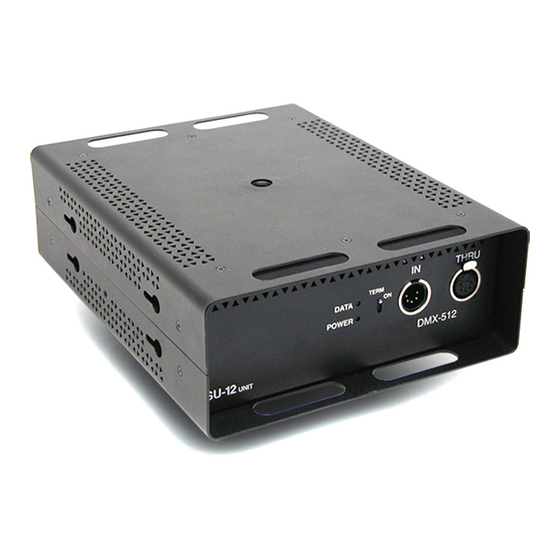
- Page 4 To simplify the choice of power supply we use the "PU" (Power Unit) to calculate the load requirements of the Chroma-Q system. The PS12 will supply up to 12 PU's, so you can plug-in 12 Chroma-Q Plus (12 x 1PU = 12PU). The individual output has a maximum capacity of 8PU.
- Page 5 Effects Gobo Rotator and Twin DMX Gobo Rotator. Control and Power Cables The Chroma-Q utilises an XLR-4 pin cable system. This is used to supply power and data transfer. Pins 1 and 4 supply 24VDC power and pins 2 and 3 supply ANSI E1.11 USITT DMX512-A control protocol with a ground drain wire to the connector shell.


Need help?
Do you have a question about the Magic Box PS12 and is the answer not in the manual?
Questions and answers