Bosch MIC IP fusion 9000i Installation Manual
Hide thumbs
Also See for MIC IP fusion 9000i:
- Operation manual (80 pages) ,
- Installation manual (54 pages) ,
- User manual (93 pages)
Table of Contents
Advertisement
Quick Links
Advertisement
Table of Contents

Related Manuals for Bosch MIC IP fusion 9000i


Summary of Contents for Bosch MIC IP fusion 9000i
- Page 1 MIC IP fusion 9000i MIC‑9502‑Z30BQS│MIC‑9502‑Z30WQS│MIC‑9502‑Z30GQS│MIC‑ 9502‑Z30BVS│MIC‑9502‑Z30WVS│MIC‑9502‑Z30GVS│MIC‑9502‑Z 30BVF│MIC‑9502‑Z30WVF│MIC‑9502‑Z30GVF│MIC‑9502‑Z30DVF │MIC‑9502‑Z30BVF9│MIC‑9502‑Z30WVF9│MIC‑9502‑Z30BVS9│ MIC‑9502‑Z30WVS9 Installation Manual...
-
Page 3: Table Of Contents
MIC IP fusion 9000i Table of contents | en Table of contents Safety About this Manual Legal Information Safety Precautions Important Safety Instructions Important Notices Use latest software Customer Support and Service Introduction Additional Products Required Additional Tools Establishing the connection... -
Page 4: Safety
Legal Information Copyright This manual is the intellectual property of Bosch Security Systems, and is protected by copyright. All rights reserved. Trademarks All hardware and software product names used in this document are likely to be registered trademarks and must be treated accordingly. -
Page 5: Safety Precautions
MIC IP fusion 9000i Safety | en Safety Precautions In this manual, the following symbols and notations are used to draw attention to special situations: Danger! High risk: This symbol indicates an imminently hazardous situation such as “Dangerous Voltage” inside the product. If not avoided, this will result in an electrical shock, serious bodily injury, or death. -
Page 6: Important Safety Instructions
® Electrical Code (NEC)), Canadian Electrical Code, Part I (also called CE Code or CSA C22.1), and all applicable local codes. Bosch Security Systems accepts no liability for any damages or losses caused by incorrect or improper installation. Warning! INSTALL EXTERNAL INTERCONNECTING CABLES IN ACCORDANCE TO NEC, ANSI/NFPA70 (FOR US APPLICATION) AND CANADIAN ELECTRICAL CODE, PART I, CSA C22.1 (FOR CAN... -
Page 7: Important Notices
Do not open the camera unit. Doing so will invalidate the warranty. – Do not point the camera at the sun. Bosch Security Systems will not be liable for any damage to cameras that have been pointed directly at the sun. - Page 8 Camera signal - Protect the cable with a primary protector if the camera signal is beyond 140 feet, in accordance with NEC800 (CEC Section 60). Environmental statement - Bosch has a strong commitment towards the environment. This device has been designed to respect the environment as much as possible.
- Page 9 MIC IP fusion 9000i Safety | en FCC suppliers Declaration of Conformity MIC IP fusion 9000i High-definition PTZ camera with thermal and visual imagers Responsible party Bosch Security Systems, Inc. 130 Perinton Parkway 14450 Fairport, NY, USA www.boschsecurity.us UL Disclaimer Underwriter Laboratories Inc.
-
Page 10: Use Latest Software
– Security advisories, that is a list of identified vulnerabilities and proposed solutions: https://www.boschsecurity.com/xc/en/support/product-security/security-advisories.html Bosch assumes no liability whatsoever for any damage caused by operating its products with outdated software components. Notice! Bosch strongly recommends upgrading to the latest firmware for the best possible functionality, compatibility, performance and security. -
Page 11: Introduction
Sales or Customer Service Representative from Bosch Security Systems. – Do not use this product if any component appears to be damaged. Please contact Bosch Security Systems in the event of damaged goods. – The original packing carton (if undamaged) is the safest container in which to transport the unit and must be used if returning the unit for service. -
Page 12: Password Protection In Camera
If you cannot connect, the unit may have reached its maximum number of connections. Depending on the device and network configuration, each unit can have up to 50 web browser connections, or up to 100 connections via Bosch Video Client or BVMS. Password protection in camera The device is password-protected. -
Page 13: Product Description
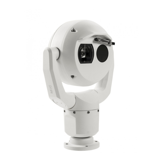
Make sure that the installation conditions comply with the specified stresses of vibration and shock as mentioned in the datasheet. The MIC IP fusion 9000i camera is a day/night, IP PTZ camera with dual optical/thermal imagers. Ruggedized and weatherproof, the camera offers a reliable, robust, and high-quality surveillance solution for extreme security applications. -
Page 14: Installation Overview
| Installation Overview MIC IP fusion 9000i Installation Overview Notice! To maintain the Type 6P rating when the camera is mounted to a MIC-DCA, installers must make sure that the user-supplied cable glands or conduit connections have Type 6P ratings. - Page 15 MIC IP fusion 9000i Installation Overview | en Depending on your installation requirements, you may need to complete the following steps: Pre-configuration (Optional) Refer to (Optional) Configuration Programming in the Shipping Box, page 30 . Mounting options Refer to Mounting Bracket Options, page 20 .
-
Page 16: Mounting
(sold separately): – MIC-9K-IP67-5PK (IP67 Connector kit for MIC IP fusion 9000i, MIC IP ultra 7100i, and MIC IP starlight 7100i cameras) To have an installation rated IP67, you must use the appropriate IP67 Connector Kit from Bosch. - Page 17 If the camera is installed in a highly exposed location where lightning strikes may occur, then Bosch recommends installing a separate lightning conductor within 0.5 m (1.6 ft) of the camera and at least 1.5 m (4.9 ft) higher than the camera. A good earth bonding connection to the camera housing itself will provide protection against damage from secondary strikes.
-
Page 18: Mounting Options
| Mounting MIC IP fusion 9000i Mounting Options See the figures that follow for illustrations of the correct and the incorrect mounting orientations of MIC cameras. MIC cameras are designed to be mounted upright (straight up) or inverted (straight down). - Page 19 The figures below illustrate the tilt range of the camera in upright orientation and in inverted orientation. 90° 90° 56° 56° 56° 56° 56° 56° Tilt range of MIC IP fusion 9000i camera Bosch Security Systems 2022-09 | 1.6 | F.01U.334.820 Installation Manual...
-
Page 20: Mounting Bracket Options
Bosch sells a complete series of mounting brackets that support multiple mounting configurations. Always use only Bosch-supplied mounts, which are designed for safe installation of your MIC camera. Refer to the MIC Series Mounting Brackets Installation Guide for complete installation instructions. - Page 21 MIC IP fusion 9000i Mounting | en Through-wall Mount Typical direct wall mount (MIC9000 on WMB mounted directly to a wall (gasket required)) Down-wall Mount Typical wall mount with SCA (MIC9000) Pole Mount The figure below identifies the three mounting accessories (each sold separately) that are necessary to mount the MIC camera on the side of a pole.
- Page 22 | Mounting MIC IP fusion 9000i Figure 5.2: Typical Pole mount configuration Typical pole mount configuration (MIC9000) Corner Mount Figure 5.3: Typical Corner mount configuration Note: Always install an SCA when you install a wall mount for any installation configuration. Route cables through the bottom of the SCA (to prevent water from running into the side or top of the SCA along the cables).
-
Page 23: Considerations For Mounting The Camera In Inverted Orientation
MIC IP fusion 9000i Mounting | en Typical corner mount configuration (MIC9000) Surface Mount Direct surface mount (upright) with base gasket (MIC9000) Direct surface mount (inverted) with base gasket + IP67 Weatherization/Connector Kit Considerations for Mounting the Camera in Inverted Orientation To change the camera orientation to “Inverted,”... - Page 24 | Mounting MIC IP fusion 9000i Apply power to the camera. Access the web browser of the camera. Access the page Configuration. Navigate to Camera > Installer Menu > Orientation. Select “Inverted.” The camera head will rotate automatically into inverted position (180°).
- Page 25 MIC IP fusion 9000i Mounting | en Figure 5.5: MIC camera mounted in inverted orientation (on pole) Bosch Security Systems 2022-09 | 1.6 | F.01U.334.820 Installation Manual...
-
Page 26: Installing The Camera Outdoors
| Installing the camera outdoors MIC IP fusion 9000i Installing the camera outdoors Cameras installed outdoors are typically exposed to surges, transients, and lightning. The details for wiring and installation are based on common practices for proper surge and lightning suppression. - Page 27 – Follow the manufacturer’s installation instructions. Camera Housings and Mounts – Use only Bosch mounts listed on the specific camera’s data sheet. – Follow all grounding for the camera housings and mounts per the installation manual. Bosch Security Systems 2022-09 | 1.6 | F.01U.334.820...
- Page 28 | Installing the camera outdoors MIC IP fusion 9000i How to ground the parapet mount Install the parapet mount per Section 2.5 of the installation mount, except for the 3/8 inch bolt at the bottom of the mount. Attach the grounded metal conduit to the parapet and connected to an outdoor rated metal junction box.
- Page 29 MIC IP fusion 9000i Installing the camera outdoors | en Figure 6.2: Grounding a parapet mount Bosch Security Systems 2022-09 | 1.6 | F.01U.334.820 Installation Manual...
-
Page 30: (Optional) Configuration Programming In The Shipping Box
| (Optional) Configuration Programming in the Shipping Box MIC IP fusion 9000i (Optional) Configuration Programming in the Shipping The camera packaging allows installers to connect the camera to the network and configure the camera still in the box. Caution! Risk of damage to camera Do not change the camera orientation to “Inverted”... -
Page 31: Optional) Configuration Programming On A Temporary Table-Top Stand
(Optional) Configuration Programming on a Temporary Table-top Stand | MIC IP fusion 9000i (Optional) Configuration Programming on a Temporary Table-top Stand Caution! Take extra care lifting or moving MIC cameras because of their weight. The camera (still in the foam) can stand temporarily on a flat, horizontal surface such as a desk or a table during initial network connection and configuration. -
Page 32: Installing A Mic Camera On A Hinged Dca
| Installing a MIC Camera on a Hinged DCA MIC IP fusion 9000i Installing a MIC Camera on a Hinged DCA The hinge feature allows installers to “hang” the camera temporarily but securely during installation for easier connection of cables/wiring before final bolts are installed. - Page 33 Installing a MIC Camera on a Hinged DCA | en 3/4” NPT 1. Attach the DCA to the mounting location using user-supplied hardware (item 1). (Bosch recommends stainless steel bolts and washers.) 2. Attach user-supplied conduit or glands to the side hole or to the bottom hole. If applicable, use the conduit adapter (male M25 to female ¾...
- Page 34 | Installing a MIC Camera on a Hinged DCA MIC IP fusion 9000i 7. For inverted installation, apply a small amount of grease to the primary O-ring to hold it in place. 8. Push the wires from the camera base into the DCA while positioning the base pin of the camera under the DCA hook (item 1).
- Page 35 MIC IP fusion 9000i Installing a MIC Camera on a Hinged DCA | en 9. Carefully tilt the camera to the side with the pin under the hook. Notice! Risk of damage to the camera! Ease the camera into position; do not allow it to fall unassisted into rotated position or allow head to slam into any surface or object! 10.
-
Page 36: Optional) Installing A Sunshield
| (Optional) Installing a Sunshield MIC IP fusion 9000i (Optional) Installing a Sunshield Quantity Component Sunshield shells Spike strips Screws Flat washers Quick Installation Guide Additional Tools Required Phillips-head screwdriver, #2, to remove factory-installed plastic screws from the camera head Torx driver, T20, for M4 Torx head screws 1. - Page 37 MIC IP fusion 9000i (Optional) Installing a Sunshield | en 4. Align the sunshield shells so that the pins slide into the bolt heads on the faceplate. 5. Ensure that the sunshield mounting holes align with the holes in the rear of the camera head.
-
Page 38: Connection
(UPS) supply is necessary. The UPS must have a Transfer Time between 2–6 ms and a Backup Runtime of greater than 5 seconds for the power level as specified on the product datasheet. Maximum wire distances from 24 VAC power supply to MIC IP fusion 9000i camera VA / Watts 14 AWG... -
Page 39: Ethernet Connections
Terminal Connector RJ45, Male High PoE (95 W) Use a midspan sold by Bosch, or a midspan that is offered as a compatible alternative. Note: Consult the National Electrical Code (NEC) or other regional standards for cable bundling requirements and limitations. -
Page 40: Camera Connections
Note: If the MIC camera will be installed directly to a mounting surface, instead of onto a MIC DCA or a MIC wall mount bracket, Bosch recommends using the connector kit for your model of camera to protect the connections against moisture and dust particles. Each kit provides components for connecting as many as 5 MIC cameras. - Page 41 MIC IP fusion 9000i Connection | en – If using a High PoE midspan power source: a. Connect one end of a Cat5e/Cat6 Shielded Twisted Pair (STP) Ethernet cable to the RJ45 connector of the camera. b. Connect the other end of the cable to the DATA + POWER OUT port on the midspan.
-
Page 42: Installing The Camera Outdoors
| Connection MIC IP fusion 9000i 11.6 Installing the camera outdoors 2022-09 | 1.6 | F.01U.334.820 Bosch Security Systems Installation Manual... -
Page 43: Typical System Configurations
MIC IP fusion 9000i Typical System Configurations | en Typical System Configurations MIC IP fusion 9000i System Configuration Options Bosch Security Systems 2022-09 | 1.6 | F.01U.334.820 Installation Manual... -
Page 44: Troubleshooting
| Troubleshooting MIC IP fusion 9000i Troubleshooting Table of Troubleshooting Issues The table below identifies issues that could occur with the camera, and how to resolve them. Note: Refer to the Error Codes section of the manual for descriptions of the error codes that appear on the OSD. - Page 45 Camera reboots frequently or Your camera has an improper network connection. intermittently Test your camera with another power supply. Check the Bosch website for a software update that might address the issue. No OSD messages appear. Bosch’s Video SDK is required. Video management software from third parties does not use the SDK.
- Page 46 | Troubleshooting MIC IP fusion 9000i Problem Explanation Solution The picture shows Check to see if there the heat images that aren’t of objects are being reflected present in the scene. off a surface causing thermal reflections. 2022-09 | 1.6 | F.01U.334.820...
-
Page 47: Maintenance
No User-serviceable Parts Except for the external wiper blade, the device contains no user-serviceable parts. Contact your local Bosch service center for device maintenance and repair. In the event of failure, the device should be removed from site for repair. -
Page 48: Replacing A Wiper Assembly
| Maintenance MIC IP fusion 9000i 14.1 Replacing a wiper assembly Put a piece of thin, protective material between the window glass and the wiper to prevent accidental damage. 2022-09 | 1.6 | F.01U.334.820 Bosch Security Systems Installation Manual... - Page 49 MIC IP fusion 9000i Maintenance | en With one hand, hold the wiper arm firmly in place to restrict rotational movement. With the other hand, using a 7mm Hex socket or nut driver, rotate the acorn nut counter- clockwise until the nut is free from the wiper shaft.
- Page 50 | Maintenance MIC IP fusion 9000i Remove the wiper spring, hub, arm, and blade assembly from the wiper shaft. 2022-09 | 1.6 | F.01U.334.820 Bosch Security Systems Installation Manual...
- Page 51 MIC IP fusion 9000i Maintenance | en Connect the new wiper arm and the new wiper hub. Insert the new blade assembly into the new wiper arm. Bosch Security Systems 2022-09 | 1.6 | F.01U.334.820 Installation Manual...
- Page 52 | Maintenance MIC IP fusion 9000i Slide the new wiper hub and the attached parts onto the wiper shaft. 2022-09 | 1.6 | F.01U.334.820 Bosch Security Systems Installation Manual...
- Page 53 MIC IP fusion 9000i Maintenance | en Slide the new wiper spring onto the wiper shaft and over the new wiper arm. Bosch Security Systems 2022-09 | 1.6 | F.01U.334.820 Installation Manual...
- Page 54 | Maintenance MIC IP fusion 9000i Apply Loctite 243 to the hole of the acorn nut. 10. Lightly thread the new acorn nut onto the wiper shaft over the new wiper spring and new wiper hub. 2022-09 | 1.6 | F.01U.334.820...
- Page 55 MIC IP fusion 9000i Maintenance | en 11. With one hand, hold the new wiper arm firmly in place to restrict rotational movement and to keep the wiper assembly parallel with the flat top of the glass. 12. With the other hand, using a 7mm Hex socket or nut driver, tighten the new acorn nut clockwise to a torque value of 1.0 Nm.
-
Page 56: Decommissioning
The device should only be passed on together with this Installation manual. 15.2 Disposal Disposal - Your Bosch product was developed and manufactured with high-quality material and components that can be recycled and reused. This symbol means that electronic and electrical appliances, which have reached the end of their working life, must be collected and disposed of separately from household waste material. -
Page 57: Technical Data
MIC IP fusion 9000i Technical data | en Technical data For product specifications, see the datasheet for your camera, available on the appropriate product pages of the Online Product Catalog at www.boschsecurity.com. Bosch Security Systems 2022-09 | 1.6 | F.01U.334.820... -
Page 58: Support Services And Bosch Academy
Support services and Bosch Academy Support Access our support services at www.boschsecurity.com/xc/en/support/. Bosch Building Technologies Academy Visit the Bosch Building Technologies Academy website and have access to training courses, video tutorials and documents: www.boschsecurity.com/xc/en/support/training/ 2022-09 | 1.6 | F.01U.334.820 Bosch Security Systems... - Page 60 Bosch Security Systems B.V. Torenallee 49 5617 BA Eindhoven Netherlands www.boschsecurity.com © Bosch Security Systems B.V., 2022 Building solutions for a better life. 202209132253...
Need help?
Do you have a question about the MIC IP fusion 9000i and is the answer not in the manual?
Questions and answers