Table of Contents
Advertisement
Quick Links
Advertisement
Table of Contents
Troubleshooting

Subscribe to Our Youtube Channel
Related Manuals for Hukseflux FHF03


Summary of Contents for Hukseflux FHF03
- Page 1 USER MANUAL FHF03 Economical foil heat flux sensor with thermal spreaders, flexible, 30 x 15 mm, with temperature sensor Copyright by Hukseflux | manual www.hukseflux.com | info@hukseflux.com Copyright by Hukseflux Thermal Sensors B.V. | www.huksefluxusa.com info@huksefluxusa.com...
-
Page 2: Warning Statements
Warning statements Putting more than 12 Volt across the sensor wiring can lead to permanent damage to the sensor. Do not use “open circuit detection” when measuring the sensor output. FHF03 manual v2108 2/35... -
Page 3: Table Of Contents
Appendix on standards for calibration Appendix on calibration hierarchy Appendix on correction for temperature dependence Appendix on measurement range for different temperatures Appendix on using FHF03 with BLK – GLD sticker series EU declaration of conformity FHF03 manual v2108 3/35... -
Page 4: List Of Symbols
List of symbols Quantities Symbol Unit Heat flux Φ W/m² Voltage output Sensitivity V/(W/m Temperature °C Thermal resistance per unit area K/(W/m²) thermal,A subscripts property of heatsink heatsink maximum value, specification limit maximum FHF03 manual v2108 4/35... -
Page 5: Introduction
It is applicable over a temperature range from –40 to +150 °C. FHF03 is often applied as part of a larger test- or measuring system. FHF03 measures heat flux through the object in which it is incorporated or on which it is mounted, in W/m . - Page 6 FHF03 sensitivity to heat flux may be different than stated on its certificate. See Chapter 2 in this manual for suggested solutions. Figure 0.2 FHF03 foil heat flux sensor being installed to measure heat flux on a computer processor FHF03 manual v2108...
- Page 7 Would you like to study energy transport / heat flux in detail? Hukseflux helps taking this measurement to the next level: order FHF03 with radiation-absorbing black and radiation- reflecting gold stickers. You can then measure convective + radiative flux with one, and convective flux only with the other.
-
Page 8: Ordering And Checking At Delivery
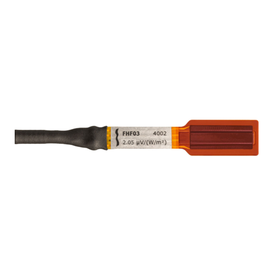
FHF03 with cable of the length as ordered • product certificate matching the instrument serial number Figure 1.2.1 FHF03’s serial number and sensitivity are visible on the sticker close to FHF03’s strain relief. The sensor is delivered with bundled cable and wire ends. FHF03 manual v2108... -
Page 9: Quick Instrument Check
Exposing the back side (the side without sticker) to heat should generate a positive signal between the red [+] and black [-] wires. Doing the same at the front side (the side with sticker), reverses the sign of the output. FHF03 manual v2108 9/35... -
Page 10: Instrument Principle And Theory
Instrument principle and theory FHF03’s scientific name is heat flux sensor. A heat flux sensor measures the heat flux density through the sensor itself. This quantity, expressed in W/m , is usually called “heat flux”. FHF03 users typically assume that the measured heat flux is representative of the undisturbed heat flux at the location of the sensor. - Page 11 Figure 2.2 Heat flux from the back side to the front side (side with sticker, logo readable) generates a positive voltage output signal FHF03 is designed such that heat flux from the back side to the front side (side with sticker, logo readable) generates a positive voltage output signal.
- Page 12 FHF03 sensitivity to heat flux may be different than stated on the certificate. In such cases, the user may choose: •...
-
Page 13: Specifications Of Fhf03
W/m , is called heat flux. Working completely passive, using a thermopile sensor, FHF03 generates a small output voltage proportional to this flux. It can only be used in combination with a suitable measurement system. Table 3.1 Specifications of FHF03 (continued on next page) - Page 14 Table 3.1 Specifications of FHF03 (started on previous page) Standard cable length Wiring 3 x copper and 1 x constantan wire, AWG 24, stranded Cable diameter 3.6 x 10 Marking 1 x sticker, showing serial number and sensitivity IP protection class...
- Page 15 Table 3.1 Specifications of FHF03 (started on previous page) VERSIONS / OPTIONS With 5 metres of cable option code = cable length in metres With black sticker applied BLK-3015 applied to the sensor at the factory to absorb radiation With gold sticker applied...
-
Page 16: Dimensions Of Fhf03
3.2 Dimensions of FHF03 Figure 3.2.1 FHF03 heat flux sensor; dimensions in x 10 sensing area with thermal spreader passive guard type T thermocouple sticker showing serial number and sensitivity strain relief cable, standard length 2 m FHF03 manual v2108... -
Page 17: Standards And Recommended Practices For Use
In many cases heat flux sensors are used for trend-monitoring. In such cases reproducibility is more important than absolute measurement accuracy. Figure 4.1.1 Example of an FHF03 foil heat flux sensor being installed for measurement on a computer processor. The sensor is mounted on a well-prepared flat surface. -
Page 18: Installation Of Fhf03
Installation of FHF03 5.1 Site selection and installation Table 5.1.1 Recommendations for installation of FHF03 heat flux sensors Location choose a location that is representative of the process that is analysed if possible, avoid exposure to sun, rain, etc. do not expose to drafts and lateral heat fluxes... - Page 19 Figure 5.1.1 Installation of FHF03 using tape to fixate the sensor and the strain relief. Extra strain relief of the cable is provided using cable tie mounts equipped with double sided tape as adhesive. As indicated in Table 5.1.1, tapes fixating the sensor are preferably taped over the passive guard area and not on the sensing area (the latter indicated by grey shading in Figure 5.1.1).
-
Page 20: Installation On Curved Surfaces
The flexibility of the FHF03 makes it perfectly suitable to be installed on singly curved surfaces. Bend the sensor in the direction indicated in Figure 5.2.1. Figure 5.2.1 Bending of an FHF03 foil heat flux sensor, in this image on a pipe. FHF03 is not suited for dynamic bending. - Page 21 Table 5.2.1 Extra recommendations for installation of FHF03 foil heat flux sensors on curved surfaces Bending bend the sensor in the direction indicated in Figure 5.2.1 Rated bending radius ≥ 25 x 10 Effect on sensitivity sensitivity increases slightly with decreasing bending radius, when bent in...
-
Page 22: Electrical Connection
A heat flux sensor should be connected to a measurement system, typically a so-called datalogger. FHF03 is a passive sensor that does not need any power. Although FHF03 is provided with a shielded cable, cables may act as a source of distortion, by picking up capacitive noise. - Page 23 U = U (Formula 5.3.2.2) Table 5.3.2.1 The electrical connection of two FHF03’s, 1 and 2, in series. In such case the sensitivity is the sum of the two sensitivities of the individual sensors. More sensors may be added in a similar manner...
- Page 24 5.3.3 Connection to read out half signals See the figure on the left: FHF03 can be connected to read out only the heat flux through the left 50 % of the sensing area or the heat flux though the right 50 % of the sensing area. This feature may be used for quality assurance purposes;...
-
Page 25: Requirements For Data Acquisition / Amplification
FHF03 are available. In case a program for similar instruments is available, this can be used. FHF03 can be treated in the same way as other heat flux sensors and thermopile pyranometers. -
Page 26: Maintenance And Trouble Shooting
The preferred way to obtain a reliable measurement is a regular critical review of the measured data, preferably checking against other measurements. Table 6.1.1 Recommended maintenance of FHF03. If possible the data analysis is done on a daily basis... -
Page 27: Trouble Shooting
Check the condition of the wires. Check the datalogger program in particular if the right sensitivity is entered. FHF03 sensitivity and serial number are shown on the product certificate and on the sticker. Check the electrical resistance of the sensor between the black [‒] and red [+] wires. -
Page 28: Calibration And Checks In The Field
On-site field calibration is possible by comparison to a calibration reference sensor. Usually mounted side by side, alternatively mounted on top of the field sensor. Hukseflux main recommendations for field calibrations are: 1) to compare to a calibration reference of the same brand and type as the field sensor... -
Page 29: Appendices
Appendices 7.1 Appendix on cable extension FHF03 is equipped with one cable, and is available in cable lengths of 2 and 5 m. Cables may act as a source of distortion by picking up capacitive noise. Keep the distance between data logger or amplifier and sensor as short as possible. -
Page 30: Appendix On Standards For Calibration
Transducers specifies in chapter 6 that a guarded hot plate, a heat flowmeter, a hot box or a thin heater apparatus are all allowed. Hukseflux employs a thin heater apparatus, uses a linear function according to X1.1 and uses a nominal temperature of 20 °C, in accordance with X2.2. -
Page 31: Appendix On Correction For Temperature Dependence
Φ = U/(S∙(1 + 0.002∙(T – 20))) (Formula 7.4.1) with Φ the heat flux in W/m², U the FHF03 voltage output in V, S the sensitivity in V/(W/m²) at 20 °C and T the FHF03 temperature. S is shown on the product certificate and on the sticker. -
Page 32: Appendix On Measurement Range For Different Temperatures
7.5 Appendix on measurement range for different temperatures The measurement range of FHF03 is specified as (-10 to +10) x 10 at 20 °C heat sink temperature. This is a very conservative specification. In reality, the maximum temperature of +150 °C is the limiting specification. The sensor temperature T in °C in a specific application depends on the heatsink temperature T... -
Page 33: Appendix On Using Fhf03 With Blk - Gld Sticker Series
For more details, see the BLK – GLD sticker series user manual. Figure 7.6.1 FHF03 heat flux sensor: with BLK-3015 and GLD-3015 stickers Table 7.6.1 Recommendations for use of FHF03 heat flux sensors with BLK – GLD sticker series Mounting when mounting FHF03 with a BLK or GLD sticker, keep the directional sensitivity in mind. -
Page 34: Eu Declaration Of Conformity
7.7 EU declaration of conformity Hukseflux Thermal Sensors B.V. Delftechpark 31 2628 XJ Delft The Netherlands in accordance with the requirements of the following directive: 2011/65/EU The Restriction of Hazardous Substances Directive hereby declare under our sole responsibility that: Product model:... - Page 35 © 2021, Hukseflux Thermal Sensors B.V. www.huksefluxusa.com Hukseflux Thermal Sensors B.V. reserves the right to change specifications without notice.
Need help?
Do you have a question about the FHF03 and is the answer not in the manual?
Questions and answers