Table of Contents
Advertisement
Quick Links
Advertisement
Table of Contents
Troubleshooting

Related Manuals for Hukseflux FHF04


Summary of Contents for Hukseflux FHF04
- Page 1 Hukseflux Thermal Sensors USER MANUAL FHF04 Foil heat flux sensor with thermal spreaders, flexible, 50 x 50 mm, with temperature sensor Copyright by Hukseflux | manual www.hukseflux.com | info@hukseflux.com Copyright by Hukseflux | manual v2101 | www.hukseflux.com | info@hukseflux.com...
-
Page 2: Cautionary Statements
Failure to comply with a caution statement may lead to risk of minor or moderate physical injuries. NOTICE Failure to comply with a notice may lead to damage to equipment or may compromise reliable operation of the instrument. FHF04 manual v2101 2/39... -
Page 3: Table Of Contents
Calibration and checks in the field Appendices Appendix on wire extension Appendix on installation of FHF04 sensor foil Appendix on using FHF04 with BLK – GLD sticker series Appendix on standards for calibration Appendix on calibration hierarchy Appendix on correction for temperature dependence... -
Page 4: List Of Symbols
List of symbols Quantities Symbol Unit Heat flux Φ W/m² Voltage output Sensitivity V/(W/m Temperature °C Thermal resistance per unit area K/(W/m²) thermal,A subscripts property of heatsink heatsink maximum value, specification limit maximum FHF04 manual v2101 4/39... -
Page 5: Introduction
Optionally, black BLK and gold GLD stickers are available to separately determine heat transport by radiation and convection. FHF04 measures heat flux through the object in which it is incorporated or on which it is mounted, in W/m . The sensor in FHF04 is a thermopile. This thermopile measures the temperature difference across FHF04’s flexible body. - Page 6 FHF04 has proven to be very robust and stable. Figure 0.2 FHF04 foil heat flux sensor being installed to measure heat flux on a pipe FHF04 calibration is traceable to international standards. The factory calibration method follows the recommended practice of ASTM C1130 - 17.
- Page 7 They can be applied to the sensor by the user or ordered pre-applied at the factory; see the BLK – GLD sticker series user manual and installation video for instructions. absorbs radiation reflects radiation Figure 0.3 FHF04 heat flux sensor: with BLK-5050 and GLD-5050 stickers See also: model FHF04SC for a self-calibrating version of FHF04 •...
-
Page 8: Ordering And Checking At Delivery
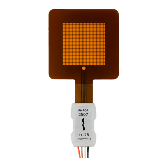
FHF04 with wires of the length as ordered • product certificate matching the instrument serial number • Figure 1.2.1 FHF04’s serial number and sensitivity are visible on the metal connection block. FHF04 is delivered with bundled wiring. FHF04 manual v2101 8/39... -
Page 9: Quick Instrument Check
Exposing the back side (the side without the dot) to heat should generate a positive signal between the red [+] and black [-] wires. Doing the same at the front side (the side with the dot), reverses the sign of the output. FHF04 manual v2101 9/39... -
Page 10: Instrument Principle And Theory
Instrument principle and theory FHF04’s scientific name is heat flux sensor. A heat flux sensor measures the heat flux density through the sensor itself. This quantity, expressed in W/m , is usually called “heat flux”. FHF04 users typically assume that the measured heat flux is representative of the undisturbed heat flux at the location of the sensor. - Page 11 The dot on the foil indicates the front side. FHF04 is designed such that heat flux from the back side to the front side generates a positive voltage output signal. The dot on the foil indicates the front side.
- Page 12 The user should analyse his own experiment and make his own uncertainty evaluation. The FHF04 rated temperature range for continuous use is -70 to +120 °C, for short intervals, a peak temperature of +150 °C is allowed. Prolonged exposure to temperatures near +150 °C can accelerate the aging process.
-
Page 13: Specifications Of Fhf04
W/m , is called heat flux. Working completely passive, using a thermopile sensor, FHF04 generates a small output voltage proportional to this flux. It can only be used in combination with a suitable measurement system. Table 3.1.1 Specifications of FHF04 (continued on next pages) - Page 14 Table 3.1.1 Specifications of FHF04 (started on previous page) Temperature sensor type T thermocouple Temperature sensor accuracy ± 2 % (of temperature in ˚C), see appendix Standard wire length Wiring 3 x copper and 1 x constantan wire, AWG 24, stranded...
- Page 15 Table 3.1.1 Specifications of FHF04 (started on previous pages) VERSIONS / OPTIONS With longer wire length option code = wire length in metres Without wires, without metal connection calibrated FHF04 sensor foil block to be soldered / connected by the user...
-
Page 16: Dimensions Of Fhf04
Dimensions of FHF04 Figure 3.2.1 FHF04 heat flux sensor; dimensions in x 10 sensing area with thermal spreaders passive guard type T thermocouple dot indicating front side metal connection block, showing serial number and sensitivity wires, standard length 2 m... -
Page 17: Standards And Recommended Practices For Use
In many cases heat flux sensors are used for trend-monitoring. In such cases reproducibility is more important than absolute measurement accuracy. Figure 4.1.1 Example of an FHF04 foil heat flux sensor being installed for measurement on an industrial pipe. The sensor is mounted on a well-prepared curved surface. -
Page 18: Installation Of Fhf04
Installation of FHF04 Site selection and installation Table 5.1.1 Recommendations for installation of FHF04 heat flux sensors Location choose a location that is representative of the process that is analysed if possible, avoid exposure to sun, rain, etc. do not expose to drafts and lateral heat fluxes... - Page 19 Figure 5.1.1 Installation of FHF04 using tape to fixate the sensor and the metal connection block. Extra strain relief on the wires is provided using cable tie mounts equipped with double sided tape as adhesive. As indicated in Table 5.1.1, tapes fixating the sensor are preferably taped over the passive guard area and not on the sensing area (the latter indicated by grey shading in Figure 5.1.1).
-
Page 20: Installation On Curved Surfaces
The flexibility of the FHF04 makes it perfectly suitable to be installed on singly curved surfaces. The sensor can be bent around any axis. Figure 5.2.1 Bending of an FHF04 foil heat flux sensor, in this image on a pipe. When measuring on curved surfaces, the same recommendations of the previous chapter apply, except that the use of thermal paste is recommended over glycerol. -
Page 21: Electrical Connection
A heat flux sensor should be connected to a measurement system, typically a so-called datalogger. FHF04 is a passive sensor that does not need any power. Wires may act as a source of distortion, by picking up capacitive noise. We recommend keeping the distance between a datalogger or amplifier and the sensor as short as possible and to keep the signal wires close to each other. - Page 22 [‒] or ground Brown thermocouple type T [+] White thermocouple type T [‒] The serial number and sensitivity of the individual sensors are shown on the FHF04 product certificate and FHF04’s metal connection block. FHF04 manual v2101 22/39...
- Page 23 5.3.3 Connection to read out half signals See the figure on the left: FHF04 can be connected to read out only the heat flux through the left half of the sensing area or the heat flux though the right half of the sensing area. This feature may be used for quality assurance purposes;...
-
Page 24: Requirements For Data Acquisition / Amplification
FHF04 are available. In case a program for similar instruments is available, this can be used. FHF04 can be treated in the same way as other heat flux sensors and (analogue) thermopile pyranometers. -
Page 25: Maintenance And Trouble Shooting
The preferred way to obtain a reliable measurement is a regular critical review of the measured data, preferably checking against other measurements. Table 6.1.1 Recommended maintenance of FHF04. If possible the data analysis is done on a daily basis... -
Page 26: Trouble Shooting
Check the condition of the wires. Check the datalogger program, in particular if the right sensitivity is entered. FHF04 sensitivity and serial number are shown on the product certificate and on the metal connection block. Check the electrical resistance of the sensor between the black [‒] and red [+] wires. -
Page 27: Calibration And Checks In The Field
On-site field calibration is possible by comparison to a calibration reference sensor. Usually mounted side by side, alternatively mounted on top of the field sensor. Hukseflux main recommendations for field calibrations are: 1) to compare to a calibration reference of the same brand and type as the field sensor... - Page 28 FHF04 manual v2101 28/39...
-
Page 29: Appendices
Appendices Appendix on wire extension FHF04 is equipped with four wires. Standard wire length is 2 m. It is possible to order FHF04 with longer wire lengths or without any wires. Wires may act as a source of distortion by picking up capacitive noise. Keep the distance between data logger or amplifier and sensor as short as possible. -
Page 30: Appendix On Installation Of Fhf04 Sensor Foil
Appendix on installation of FHF04 sensor foil FHF04 can optionally be ordered without wires and without metal connection block. The user should ensure a good connection to the sensor by either soldering wires or alternatively, using a FFC / FPC ZIF connector. See Table 7.2.1 and 7.2.2 for recommendations. - Page 31 Table 7.2.1 recommendations for soldering of FHF04 sensor foils Wire use insulated wires of preferably AWG24 see Figure 7.2.1 for which material to use on which contact Preparation clean soldering pad before soldering with isopropyl alcohol (IPA) Solder material preferably use lead free solder Soldering use a soldering temperature of max 350 °C...
- Page 32 FFC / FPC (Flat Flex Cable / Flexible Printed Circuit) Connector variant ZIF (Zero Insertion Force) Number of contacts 4 contacts Pitch 2.54 x 10 External environment use FHF04 sensor foils with connector in a dry and stable environment FHF04 manual v2101 32/39...
-
Page 33: Appendix On Using Fhf04 With Blk - Gld Sticker Series
For more details, see the BLK – GLD sticker series user manual. Figure 7.3.1 FHF04 heat flux sensor: with BLK-5050 and GLD-5050 stickers Table 7.3.1 Recommendations for use of FHF04 heat flux sensors with BLK – GLD stickers Mounting when mounting an FHF04 with a BLK or GLD sticker, keep the directional... -
Page 34: Appendix On Standards For Calibration
Transducers specifies in chapter 6 that a guarded hot plate, a heat flowmeter, a hot box or a thin heater apparatus are all allowed. Hukseflux employs a thin heater apparatus, uses a linear function according to X1.1 and uses a nominal temperature of 20 °C, in accordance with X2.2. -
Page 35: Appendix On Correction For Temperature Dependence
Φ = U/(S∙(1 + 0.002∙(T – 20))) (Formula 7.6.1) with Φ the heat flux in W/m², U the FHF04 voltage output in V, S the sensitivity in V/(W/m²) at 20 °C and T the FHF04 temperature. S is shown on the product certificate and on FHF04’s metal connection block . -
Page 36: Appendix On Measurement Range For Different Temperatures
Appendix on measurement range for different temperatures The measurement range of FHF04 is specified as (-10 to +10) x 10 at 20 °C heat sink temperature. This is a very conservative specification. In reality, the rated temperature for continuous use of +120 °C is the limiting specification. -
Page 37: Appendix On Temperature Measurement Accuracy
Appendix on temperature measurement accuracy FHF04 has an integrated thermocouple to measure temperature of the object under test. This thermocouple is supplied as a secondary measurement, in addition to the main heat flux measurement. The FHF04 thermocouple wires are specified as a type T thermocouple, IEC 60584- 1:2013 class 2. -
Page 38: Eu Declaration Of Conformity
EU declaration of conformity Hukseflux Thermal Sensors B.V. Delftechpark 31 2628 XJ Delft The Netherlands in accordance with the requirements of the following directive: 2011/65/EU, The Restriction of Hazardous Substances Directive (EU) 2015/863 hereby declare under our sole responsibility that:... - Page 39 © 2021, Hukseflux Thermal Sensors B.V. www.hukseflux.com Hukseflux Thermal Sensors B.V. reserves the right to change specifications without notice.
Need help?
Do you have a question about the FHF04 and is the answer not in the manual?
Questions and answers