
Related Manuals for Cooper & Hunter Supreme CH-S18FTXAM2S


Summary of Contents for Cooper & Hunter Supreme CH-S18FTXAM2S
- Page 1 Change for Life Supreme Air-to-Air Heat Pump Service Manual Models: CH-S18FTXAM2S CH-S24FTXAM2S (Refrigerant R32)
-
Page 2: Table Of Contents
Service Manual Table of Contents Part Ⅰ : Technical Information ................. 1 1. Summary ..........................1 2. Specifications ........................2 2.1 Specification Sheet ........................2 2.2 Operation Characteristic Curve ....................4 2.3 Capacity Variation Ratio According to Temperature ..............4 2.4 Cooling and Heating Data Sheet in Rated Frequency ............... - Page 3 Service Manual 9. Maintenance ........................48 9.1 Error Code List ...........................48 9.2 Procedure of Troubleshooting ....................55 9.3 Maintenance Method for Normal Malfunction ................69 10. Exploded View and Parts List ................71 10.1 Indoor Unit ..........................71 10.2 Outdoor Unit ..........................73 11.
-
Page 4: Part Ⅰ : Technical Information
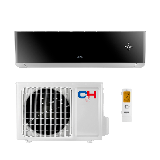
Service Manual Part Ⅰ : Technical Information 1. Summary Indoor Unit: Outdoor Unit: Remote Controller: MODE ON/OFF Technical Information... -
Page 5: Specifications
Service Manual 2. Specifications 2.1 Specification Sheet Model CH-S18FTXAM2S CH-S24FTXAM2S Rated Voltage 220-240 220-240 Power Rated Frequency 50/60 50/60 Supply Phases Power Supply Mode Outdoor Outdoor Cooling Capacity 5300 7000 Heating Capacity 5570 7000 Cooling Power Input 1320 1840 Heating Power Input 1320 1750 Cooling Power Current... - Page 6 Service Manual ZHUHAI LANDA COMPRESSOR ZHUHAI LANDA COMPRESSOR Compressor Manufacturer/Trademark CO., LTD CO., LTD Compressor Model QXFT-D20zF030 QXFT-D20zF030 Compressor Oil FW68DA FW68DA Compressor Type Rotary Rotary L.R.A. Compressor RLA 10.5 Compressor Power Input 2260 2050 Overload Protector Throttling Method Electron expansion valve Electron expansion valve Operation Temp 16~30...
-
Page 7: Operation Characteristic Curve
Service Manual 2.2 Operation Characteristic Curve Cooling Heating Cooling Heating Condition Condition Indoor:DB 20°C Indoor:DB27°C WB19°C Indoor air flow: Super High Indoor air flow: Super High Pipe length:5 or 7.5m Pipe length:5 or 7.5m Compressor Frequency(Hz) Compressor Frequency(Hz) 2.3 Capacity Variation Ratio According to Temperature Cooling Heating Condition... -
Page 8: Cooling And Heating Data Sheet In Rated Frequency
Service Manual 2.4 Cooling and Heating Data Sheet in Rated Frequency Cooling: Rated cooling Pressure of gas pipe Inlet and outlet pipe Compressor condition(°C) connecting indoor and temperature of heat Fan speed of Fan speed of Model frequency (DB/WB) outdoor unit exchanger indoor unit outdoor unit... -
Page 9: Outline Dimension Diagram
Service Manual 3. Outline Dimension Diagram 3.1 Indoor Unit Φ55 Φ55 Φ70 Φ70 Φ55 Φ55 Unit:mm Model 18/24K 1101 Φ70 Φ70 Technical Information... -
Page 10: Outdoor Unit
Service Manual 3.2 Outdoor Unit 1000 Unit:mm Technical Information... -
Page 11: Refrigerant System Diagram
Service Manual 4. Refrigerant System Diagram INDOOR UNIT OUTDOOR UNIT GAS SIDE 3-WAY VALVE 4-Way valve Discharge HEAT EXCHANGE (EVAPORATOR) Accumlator Suction COMPRESSOR HEAT EXCHANGE (CONDENSER) Intercooler LIQUID SIDE Electron Strainer Strainer Strainer Capillary Strainer 2-WAY VALVE expansion valve COOLING HEATING Connection pipe specification: Liquid pipe:1/4"... -
Page 12: Electrical Part
Service Manual 5. Electrical Part 5.1 Wiring Diagram ●Instruction Symbol Symbol Color Symbol Symbol Color Symbol Name White Green Jumper cap Yellow Brown COMP Compressor Blue Grounding wire YEGN Yellow/Green Black Note: Jumper cap is used to determine fan speed and the swing angle of horizontal lover for this model. ●... - Page 13 Service Manual ● Outdoor Unit 600007000844 600007000800 These wiring diagrams are subject to change without notice; please refer to the one supplied with the unit. Technical Information...
-
Page 14: Pcb Printed Diagram
Service Manual 5.2 PCB Printed Diagram ● Top view Name Neutral wire Needle stand for indoor fan Auto button Up&down swing motor left&right swing motor Interface of temperature sensor Terminal for display board connection Terminal of jumper cap Communication wire Connect earthing wire(only for the mode with this function) 11 Fuse... - Page 15 Service Manual ● Top view Terminal of compressor wire Terminal of low pressure protection Terminal of compressor overload protection Te r m i n a l o f o u t d o o r temperature sensor Terminal of outdoor fan Terminal of 4-way valve Communication wire with indoor unit...
- Page 16 Service Manual ● Top view Name Interface of compressor Interface of temperature sensor Te r m i n a l o f c o m p r e s s o r overload protection Low-temperature cooling sensor Cooling A valve Cooling B valve Interface of outdoor motor Interface of 2-way valve...
-
Page 17: Function And Control
Service Manual 6. Function and Control 6.1 Remote Controller Introduction Buttons on Remote Controller ON/OFF button FAN button ON/OFF button MODE button FAN button +/- button MODE button TURBO button +/- button button TURBO button button button CLOCK button button TIMER ON/ TIMER OFF button CLOCK button... - Page 18 ATUO Service Manual 2. FAN button Low fan Medium-low fan Medium fan Medium-high fan High fan Press this button, Auto, Low, Medium-low, Medium, Medium-high, High speed can be circularly selected. After powered on, Auto fan speed is default. Under DRY mode, Low fan speed only can be set up. ATUO Note: It’s Low fan speed under Dry mode.
- Page 19 Service Manual 10. TEMP button Press this button, you can see indoor set temperature, indoor ambient temperature or outdoor ambient temperature on indoor unit’s display. The setting on remote controller is selected circularly as below: no display When selecting " "...
- Page 20 Service Manual ●Sleep 3- the sleep curve setting under Sleep mode by DIY: (1) Under Sleep 3 mode, press "Turbo" button for a long time, remote control enters into user individuation sleep setting status, at this time, the time of remote control will display "1hour ", the setting temperature "88" will display the corresponding temperature of last setting sleep curve and blink (The first entering will display according to the initial curve setting value of original factory);...
- Page 21 Service Manual 28.WIFI Function Press "MODE" and "TURBO" button simultaneously to turn on or turn off WIFI function. When WIFI function is turned on, the " " icon will be displayed on remote controller; Long press "MODE" and "TURBO" buttons simultaneously for 10s, remote controller will send WIFI reset code and then the WIFI function will be turned on.
-
Page 22: Operation Of Smart Control (Smart Phone, Tablet Pc)
Service Manual 6.3 Operation of Smart Control (Smart Phone, Tablet PC) Operation Instructions Download and install APP Scan the following QR code with your smart phone and download Wifi Smart. Install the APP according to its guidance. When successfully installed, your smart phone homepage will show this icon User of IOS system can search for the Wifi Smart in Apple store to download the Apple version APP. - Page 23 Service Manual 2.Configuration method for Android phones 4 steps of configuration Step 1: Enter homepage "Device", and then tap at the top right corner. Select "Add device" and enter the page "Add device". Tap "Manual configuration" and enter the page "Manual configuration". Step 2: Tap "Next"...
- Page 24 Service Manual NOTE: After configuration is completed, the air conditioner hot spot connected to your phone will disappear. You should reconnect your phone to the home WiFi router to realize long-distance control.The above configuration only needs onephone. Other types of phones shall install this APP, connect with the air conditioner hot spot or wireless router of WiFi air conditioner.
- Page 25 Service Manual If the name of router or the password is wrong, Wifi Smart can’t connect to the wireless router. 2 mins later, please conduct the configuration operation again. Reset Wi-Fi adaptor by pointing you remote at the indoor unit and holding the mode and Turbo buttons on your remote control for 10 seconds and until you hear the beep.
- Page 26 Service Manual 2.Personal settings Purpose: Set name (device name, preset name, etc.) and images (device image) in order to identify a user easily. (1) Set device name After quick configuration, a list of controllable smart devices will be generated. Default name for air conditioner is the last 8 numbers of the air condtioner mac address.
- Page 27 Service Manual (2) Set preset name Step 1: Tap at the top right corner of the homepage "Device". Select "Add preset" and enter the page "Preset edit". Step 2: Choose the time. Tap "Name". As shown in the picture, its name is "baby room". For timer type, select "On". Then select the repeating days.
- Page 28 Service Manual Tap "babyroom" and enter the page of air conditioner control. Tap to turn on the control switch. to increase or decrease temperature. Tap to change working mode. Tap to enter the page of fan speed adjustment. and go around the circle to adjust fan speed. Step 2: Advanced settings to enter advanced settings.
- Page 29 Service Manual Continue to select the next execution device as instructed above. Tap to set the interval. Tap "Save". Tap the scene picture displayed on homepage "Device" to send the command. Then the scene "Back home" will be in execution. You may view the execution condition of the scene. (3) Preset includes single-device preset and multi-device preset Single-device preset: This can preset a certain device to be On/Off at a specific time.
- Page 30 Service Manual Tap "Name" to customize the preset name. Preset device can’t be selected and it will default to "babyroom". Select "On" for the timer type. Select repeating days to complete the preset. Multi-device preset: This can preset multiple devices to execute a command at a specific time. Please refer to the instructions as how to set preset time, name, timer type and repeating days for a single device.
- Page 31 Service Manual Tap "Temperature" to enter the page "Select temperature parameter". Slide up or down to adjust temperature. Tap "Upper limit" or "Lower limit". Tap "Mode" and "On/Off" to select the status of master device. Then tap "Save". Step 2: Set time parameter for linkage. Tap "Time parameter" to enter the page "Set time". Slide rightwards to turn on the setting time.
- Page 32 Service Manual Tap the name of device that you want to control. Tap "ON" or "OFF" and then tap "Save" to complete the linkage. Tap "Save" and then repeat the above steps to set linkage of several scenes. 4.Menu functions Menu functions (Share, Set, History, Feedback) (1) Share: To share quick configuration information and unit’s information, including local export and local import.
- Page 33 Service Manual Step 2: Another smart phone to be imported. Tap the model name and wait for the download. Notice: This function requires that the two phones are of the same operating system. They are either Android phones or Apple phones,and are connecting to the same wireless router.
- Page 34 Service Manual (3) Settings User can set vibration, message alerts, server, updates, etc. The server setting here must be the same as the server setting in "Configuration" mentioned before. Otherwise, remote control will be invalid. (4) Help Please refer to “Help” of APP for the instruction of the latest functions. Installation and Maintenance...
-
Page 35: Brief Description Of Modes And Functions
Service Manual 6.4 Brief Description of Modes and Functions 1. Temperature Parameters ◆ Indoor preset temperature (T preset ◆ Indoor ambient temperature (T amb. 2. Basic Functions Once energized, in no case should the compressor be restarted within less than 3 minutes. In the situation that memory function is available, for the first energization, if the compressor is at stop before de-energization, the compressor will be started without a 3-minute lag;... - Page 36 Service Manual ◆ When compressor is running (not including each malfunction and protection): a.When outdoor ambient temperature≥20°C(68°F) and indoor fan speed is low or medium, the fan speed will turn to high; if indoor fan speed is high or super high, it will keep the same. b.When outdoor ambient temperature≤18°C(64.4°F) , the fan speed will resume set fan speed.
- Page 37 Service Manual c.For heating and cooling unit, when 22°C(71.6°F)<Tindoor ambient<26°C(78.8°F) (for cooling only unit, 22°C(71.6°F)<Tindoor ambient<26°C)(78.8°F), it will keep the original running mode. If the unit is energized for the first time, it will run in fan mode. ② Protection a.
- Page 38 Service Manual 1. In cooling mode: 1.1 When the initial set temperature is16-23°C(60.8~73.4°F),the temperature will rise 1°C(1.8°F) by every hour after sleep function is set;the temperature will not change after rising 3°C(5.4°F) ;after running for 7hours,the temperature will decrease1°C(1.8°F) and it will not change after that.
- Page 39 Service Manual 1. Under heating mode: auto speed under heating or auto heating mode: a. When T ≤T +1°C(1.8°F), indoor fan will operate at high speed; amb. preset b. When T +1°C(1.8°F)<T <T +3°C(5.4°F), indoor fan will operate at medium speed; preset amb.
-
Page 40: Part Ⅱ : Installation And Maintenance
Service Manual Part Ⅱ : Installation and Maintenance 7. Notes for Installation and Maintenance Safety Precautions: 10. If the power cord or connection wire is not long enough, please get the specialized power cord or connection wire Important! from the manufacture or distributor. Prohibit prolong the wire by yourself. - Page 41 Service Manual To ensure safety, please be mindful of the following precautions. Warnings 1. When installing or relocating the unit, be sure to keep the refrigerant circuit free from air or substances other than the specified refrigerant. Any presence of air or other foreign substance in the refrigerant circuit will cause system pressure rise or compressor rup- ture, resulting in injury.
- Page 42 Service Manual Safety Operation of Flammable Refrigerant Qualification requirement for installation and maintenance man ●All the work men who are engaging in the refrigeration system should bear the valid certification awarded by the authoritative organization and the qualification for dealing with the refrigeration system recognized by this industry. If it needs other technician to maintain and repair the appliance, they should be supervised by the person who bears the qualification for using the flammable refrigerant.
- Page 43 Service Manual Main Tools for Installation and Maintenance 1. Level meter, measuring tape 2. Screw driver 3. Impact drill, drill head, electric drill 4. Electroprobe 5. Universal meter 6. Torque wrench, open-end wrench, inner hexagon spanner 7. Electronic leakage detector 8.
-
Page 44: Installation
Service Manual 8. Installation 8.1 Installation Dimension Diagram Space to the wall Space to the wall At least 5 7/8 At least 5 7/8 Drainage pipe Installation and Maintenance... - Page 45 Service Manual Installation procedures Start installation Preparation before installation Read the requirements select installation Prepare tools for electric connection location Select indoor unit Select outdoor unit installation location installation location Install the support of outdoor unit Install wall-mounting (select it according to the actual situation) frame, drill wall holes Connect pipes of indoor Fix outdoor unit...
-
Page 46: Installation Parts-Checking
Service Manual 8.4 Electric Connection Requirement 8.2 Installation Parts-checking 1. Safety Precaution Name Name (1) Must follow the electric safety regulations when installing Indoor unit Sealing gum the unit. Outdoor unit Wrapping tape (2) According to the local safety regulations, use qualified Support of outdoor power supply circuit and air switch. - Page 47 Service Manual in the holes. 5. Connect the Pipe of Indoor Unit (3) Fix the wall-mounting frame on the wall with tapping screws (1) Aim the pipe joint at the corresponding bellmouth.(As show (ST4.2X25TA) and then check if the frame is firmly installed by in Fig.5) pulling the frame.
- Page 48 Service Manual 7. Connect Wire of Indoor Unit 8. Bind up Pipe (1) Open the panel, remove the screw on the wiring cover and (1) Bind up the connection pipe, power cord and drain hose then take down the cover.(As show in Fig.11) with the band.(As show in Fig.14) (2) Reserve a certain length of drain hose and power cord Screw...
-
Page 49: Installation Of Outdoor Unit
Service Manual 8.6 Installation of Outdoor Unit (3) Pretightening the union nut with hand. (4) Tighten the union nut with torque wrench . 1. Fix the Support of Outdoor Unit(Select it according to Refer to the following table for wrench moment of force: the actual installation situation) (1) Select installation location according to the house structure. -
Page 50: Vacuum Pumping And Leak Detection
Service Manual Note: 2. Leakage Detection (1) With leakage detector: (1) The through-wall height of drain hose shouldn't be higher Check if there is leakage with leakage detector. than the outlet pipe hole of indoor unit.(As show in Fig.25) (2) With soap water: (2) Slant the drain hose slightly downwards. -
Page 51: Maintenance
Service Manual 9. Maintenance 9.1 Error Code List Display Method of Outdoor Display Method of Indoor Unit Unit Indicator has 3 kinds of Indicator Display (during display status and during Malfunction blinking, ON 0.5s and OFF Dual-8 A/C status Possible Causes blinking, ON 0.5s and OFF Name 0.5s) - Page 52 Service Manual Display Method of Outdoor Display Method of Indoor Unit Unit Indicator has 3 kinds of Indicator Display (during display status and during Malfunction blinking, ON 0.5s and OFF Dual-8 A/C status Possible Causes blinking, ON 0.5s and OFF Name 0.5s) Code...
- Page 53 Service Manual Display Method of Outdoor Display Method of Indoor Unit Unit Indicator has 3 kinds of Indicator Display (during display status and during Malfunction blinking, ON 0.5s and OFF Dual-8 A/C status Possible Causes blinking, ON 0.5s and OFF Name 0.5s) Code...
- Page 54 Service Manual Display Method of Outdoor Display Method of Indoor Unit Unit Indicator has 3 kinds of Indicator Display (during display status and during Malfunction blinking, ON 0.5s and OFF Dual-8 A/C status Possible Causes blinking, ON 0.5s and OFF Name 0.5s) Code...
- Page 55 Service Manual Display Method of Outdoor Display Method of Indoor Unit Unit Indicator has 3 kinds of Indicator Display (during display status and during Malfunction blinking, ON 0.5s and OFF Dual-8 A/C status Possible Causes blinking, ON 0.5s and OFF Name 0.5s) Code...
- Page 56 Service Manual Display Method of Outdoor Display Method of Indoor Unit Unit Indicator has 3 kinds of Indicator Display (during display status and during Malfunction blinking, ON 0.5s and OFF Dual-8 A/C status Possible Causes blinking, ON 0.5s and OFF Name 0.5s) Code...
- Page 57 Service Manual Display Method of Indoor Unit Display Method of Outdoor Unit Indicator Display (during Indicator has 3 kinds of display blinking, ON 0.5s and OFF status and during blinking, ON Dual-8 Malfunction A/C status Possible Causes 0.5s) 0.5s and OFF 0.5s Code Name Operation...
-
Page 58: Procedure Of Troubleshooting
Service Manual 9.2 Procedure of Troubleshooting 1. Malfunction of Temperature Sensor F1, F2 Main detection points: ● Is the wiring terminal between the temperature sensor and the controller loosened or poorly contacted? ● Is there short circuit due to trip-over of the parts? ●... - Page 59 Service Manual 2. Malfunction of Blocked Protection of IDU Fan Motor H6 Main detection points: ● SmoothlyIs the control terminal of PG motor connected tightly? ● SmoothlyIs the feedback interface of PG motor connected tightly? ● The fan motor can't operate? ●...
- Page 60 Service Manual 3. Malfunction of Protection of Jumper Cap C5 Main detection points: ● Is there jumper cap on the mainboard? ● Is the jumper cap inserted correctly and tightly? ● The jumper is broken? ● The motor is broken? ●...
- Page 61 Service Manual 4. Malfunction of Overcurrent Protection E5 Main detection points: ● Is the supply voltage unstable with big fluctuation? ● Is the supply voltage too low with overload? ● Hardware trouble? Malfunction diagnosis process: Start Normal fluctuation should be within 10 % Is malfunction Is the supply voltage unstable of the rated voltage on the nameplate...
- Page 62 Service Manual 5. Communication Malfunction E6 Start Cut off power supply. Check if connection line of IDU and ODU and the wire inside electric box are correctly connected. Connect the line Correct connection? according to Malfunction eliminated? wiring diagram. Main board matches Match correctly with display board? Main board of Malfunction eliminated?
- Page 63 Service Manual 6. Malfunction of detecting plate(WIFI) JF 5. Malfunction of detecting plate(WIFI) JF Start check if the connection wire are correctly connected detecting Replace the plate with the same model Is malfunction eliminated Replace the mainboard with the same model The end Installation and Maintenance...
- Page 64 Service Manual Outdoor Unit 1. Capacity charging malfunction (outdoor unit malfunction) (AP1 below means control board of outdoor unit) Main detection points: ● Detect if the voltage of L and N terminal of XT wiring board is between 210VAC-240VAC by alternating voltage meter; ●...
- Page 65 Service Manual 2. IPM protection(H5), desynchronizing malfunction(H7), overcurrent of compressor phase current (P5) (AP1 below means control board of outdoor unit) Main detection points: ● Is voltage input within the normal range ● If the control board AP1 is well connected with compressor COMP? If they are loosened? If the connection sequence is correct? ●...
- Page 66 Service Manual 3. High temperature and overload protection (E8)(AP1 below means control board of outdoor unit) Main detection points: ● If the outdoor ambient temperature is in normal range; ● If the indoor and outdoor fan are running normally; ● If the radiating environment of indoor and outdoor unit is good. E8 is displayed Normal protection, please If the outdoor...
- Page 67 Service Manual 4. Start-up failure (LC) (AP1 below means control board of outdoor unit) Main detection points: ● If the compressor wiring is correct? ● If the stop time of compressor is sufficient? ● If the compressor is damaged? ● If the refrigerant charging amount is too much? Turn on the unit The stop time is not sufficient and If the stop time of compressor...
- Page 68 Service Manual 5. Overload and high discharge temperature malfunction Main detection points: ● If the electronic expansion valve is connected well? Is the electronic expansion valve damaged? ● If the refrigerant is leaked? ● The compressor overload protection terminal is not connected well with the mainboard? ●...
- Page 69 Service Manual H3 or E4 is displayed 30min after power off the unit If the overload protector SAT is well connected? Under ambient temperature, test the resistance of overload protector with ohmmeter; resistance value should be<1000ohm Connect wire If the wiring terminal FA of electronic according to wiring expansion valve is well connected? diagram...
- Page 70 Service Manual 6. PFC (correction for power factor) malfunction (outdoor unit malfunction) Main detection points: ● Check if power plug is connected well with the socket ● Check if the reactor of outdoor unit is damaged? Malfunction diagnosis process: start If power plug is connected Is the malfunction Connect the plug correctly...
- Page 71 Service Manual 7. Communication malfunction (E6) Main detection points: ● Check if the connection wire and the built-in wiring of indoor and outdoor unit are connected well and without damage; ● If the communication circuit of indoor mainboard is damaged? If the communication circuit of outdoor mainboard (AP1) is damaged? Malfunction diagnosis process: If the unit operates normally before malfunction...
-
Page 72: Maintenance Method For Normal Malfunction
Service Manual 9.3 Maintenance Method for Normal Malfunction 1. Air Conditioner Can't be Started Up Possible Causes Discriminating Method (Air conditioner Status) Troubleshooting Confirm whether it's due to power failure. If yes, No power supply, or poor After energization, operation indicator isn’t bright wait for power recovery. - Page 73 Service Manual 4. ODU Fan Motor Can't Operate Possible causes Discriminating method (air conditioner status) Troubleshooting Connect wires according to wiring diagram to Wrong wire connection, or poor Check the wiring status according to circuit make sure all wiring terminals are connected connection diagram firmly...
-
Page 74: Exploded View And Parts List
Service Manual 10. Exploded View and Parts List 10.1 Indoor Unit MODE ON/OFF The component picture is only for reference; please refer to the actual product. Installation and Maintenance... - Page 75 Service Manual Part Code Description CH-S18FTXAM2S CH-S24FTXAM2S Front Panel(low display) 200003000063 200003000063 Filter Sub-Assy 11012007 11012007 Front Case Sub-Assy 0000020006401 0000020006401 Axile Bush 10542036 10542036 Guide Louver 10512503 10512503 Ring of Bearing 26152025 26152025 O-Gasket of Cross Fan Bearing 76512203 76512203 Cross Flow Fan 10352057...
-
Page 76: Outdoor Unit
Service Manual 10.2 Outdoor Unit The component picture is only for reference; please refer to the actual product. Installation and Maintenance... - Page 77 Service Manual Part Code Description CH-S18FTXAM2S CH-S18FTXAM2S Front Grill 22415011 22415011 Fan Motor 15010400000102 15010400000102 Electric Box (Fireproofing) Radiator 49015215 4901521501 Main Board 300027000109 300027000308 Electric Box Assy 100002001814 100002000609 Electric Box Cover 20125002 20125002 Terminal Board 420101943 420101943 Handle 26233053 26233053 Left Side Plate...
-
Page 78: Removal Procedure
Service Manual 11. Removal Procedure Caution: discharge the refrigerant completely before removal. 11.1 Removal Procedure of Indoor Unit Step Procedure 1.Remove filter Panel Open the panel. Loosen the clasp shown and then pull the left filter and right filer outwards to remove them. Left filter and right filer 2.Remove horizontal louver Push out the axile bush on horizontal... - Page 79 Service Manual Step Procedure 3.Remove display and panel Screws Screws that are locking the display board. Display Separate the display board from the front Panel panel. Open the front panel; separate the panel rotation shaft from the groove fixing the front panel and then removes the front panel.
- Page 80 Service Manual Step Procedure 7.Remove cold plasma generator Cold plasma generator Screws that are locking the cold plasma Screw generator.Separate the display board from the evaporator assy. 8.Remove temperature sensor and grounding wire Temperature sensor Grounding wire Cut off the tieline which binding the temperature sensor and grounding wire on the evaporator, and then pull out the indoor tube temperature sensor from the...
- Page 81 Service Manual Step Procedure 11.Electric box assy Remove the screw fixing electric box assy and then remove the electric box assy. Electric box assy Screw 12.Remove connection pipe clamp Screw Connection pipe clamp At the back of the unit, remove the screw fixing connection pipe clamp and then remove the connection pipe clamp.
- Page 82 Service Manual Step Procedure 15.Remove motor and cross flow blade Motor clamp Remove the screws fixing motor clamp Screws and then remove the motor clamp. Remove the screws at the connection place of cross flow blade and motor; lift the motor and cross flow blade upwards to remove them.
-
Page 83: Removal Procedure Of Outdoor Unit
Service Manual 11.2 Removal Procedure of Outdoor Unit Steps Procedure 1.Remove handle Twist off the screws used for fixing the handle and v alve cover , pull the handle and v alve cover up ward to remove it. handle valve cover 2.Remove top panel top panel Remove the screws connecting the top... - Page 84 Service Manual Steps Procedure 4.Remove grille and panel Twist off the screws connecting the grille and panel, and then remove the grille. Twist off the screws connecting the panel, chassis and motor support with screwd-river, and then remove the panel. grille panel 5.Remove right side plate...
- Page 85 Service Manual Steps Procedure 7.Remove electric box electric box Twist off the screws on electric box, cut off the tieline with scissors or pliers, pull out the wiring terminal, pull it upwards to remove the electric box. Twist off the screws on electric box (fireproofing) electric box with screwdriver, and then remove the electric (fireproofing)
- Page 86 Service Manual Steps Procedure 9.Remove motor support Twist off the tapping screws fixingthe motor support, pull it upwardsand then remove the motor support. motor support 10.Remove isolation sheet Twist off the screws connecting isolation sheet and end plate of condenser and chassis, and then remove the isolation sheet.
- Page 87 Service Manual Steps Procedure 12.Remove gas valve and liquid valve Twist off the 2 bolts fixing the valve sub-assy. Unsolder the soldering joint between gas valve and air-return pipe and then remove the gas valve.(note: when unsoldering the soldering joint, wrap the gas valve with wet cloth completely to gas valve avoid the damage to valve, and release all...
- Page 88 Service Manual Steps Procedure 15.Remove left side plate Twist off the screws connecting the left side plate and chassis with screwdriver, and then remove the left side plate. left side plate 16.Remove chassis and condenser Pull it upwards to separate the chassis and condenser.
-
Page 89: Appendix
Service Manual Appendix: Appendix 1: Reference Sheet of Celsius and Fahrenheit Conversion formula for Fahrenheit degree and Celsius degree: Tf=Tcx1.8+32 Set temperature Fahrenheit Fahrenheit Fahrenheit display Fahrenheit display Fahrenheit display Fahrenheit Celsius(°C) Celsius(°C) Celsius(°C) temperature (°F) temperature (°F) temperature (°F) (°F) (°F) (°F) -
Page 90: Appendix 3: Pipe Expanding Method
Service Manual Appendix 3: Pipe Expanding Method Pipe Note: Pipe cutter Improper pipe expanding is the main cause of refrigerant leakage.Please expand the pipe according to the following steps: Leaning Uneven Burr A:Cut the pip ● Confirm the pipe length according to the distance of indoor unit and outdoor unit. ●... -
Page 91: Appendix 4: List Of Resistance For Temperature Sensor
Service Manual Appendix 4: List of Resistance for Temperature Sensor Resistance Table of Ambient Temperature Sensor for Indoor and Outdoor (15K) Temp( C) Resistance(kΩ) Temp( C) Resistance(kΩ) Temp( Resistance(kΩ) Temp( Resistance(kΩ) 138.1 18.75 3.848 1.071 128.6 17.93 3.711 1.039 121.6 17.14 3.579 1.009... - Page 92 Service Manual Resistance Table of Tube Temperature Sensors for Indoor and Outdoor (20K) Temp( C) Resistance(kΩ) Temp( C) Resistance(kΩ) Temp( Resistance(kΩ) Temp( Resistance(kΩ) 181.4 25.01 5.13 1.427 171.4 23.9 4.948 1.386 162.1 22.85 4.773 1.346 153.3 21.85 4.605 1.307 20.9 4.443 1.269 137.2...
- Page 93 Service Manual Resistance Table of Discharge Temperature Sensor for Outdoor (50K) Temp( C) Resistance(kΩ) Temp( Resistance(kΩ) Temp( C) Resistance(kΩ) Temp( Resistance(kΩ) 853.5 18.34 4.75 799.8 93.42 17.65 4.61 89.07 16.99 4.47 703.8 84.95 16.36 4.33 660.8 81.05 15.75 4.20 620.8 77.35 15.17 4.08...
Need help?
Do you have a question about the Supreme CH-S18FTXAM2S and is the answer not in the manual?
Questions and answers