Table of Contents
Advertisement
EN
For proper operation, please read and keep this manual carefully.
Эксклюзивный представитель климатического оборудования Cooper&Hunter
в Херсоне и Херсонской области магазин «Домотроника» www.ch.ks.ua
Designed by Cooper&Hunter International Corporation, Oregon, USA
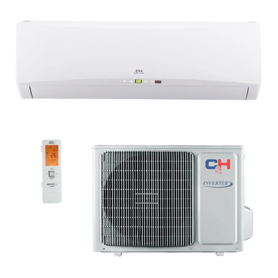
OWNER'S MANUAL
HEAT PUMP AIR TO AIR
ICY Series (With WIFI)
M ODELS :
www.cooperandhunter.com
CH-S09FTXTB-W
CH-S12FTXTB-W
CH-S18FTXTB-W
CH-S24FTXTB-W
Advertisement
Table of Contents

Subscribe to Our Youtube Channel
Related Manuals for Cooper & Hunter CH-S09FTXTB-W


Summary of Contents for Cooper & Hunter CH-S09FTXTB-W
- Page 1 OWNER’S MANUAL HEAT PUMP AIR TO AIR ICY Series (With WIFI) M ODELS : CH-S09FTXTB-W CH-S12FTXTB-W CH-S18FTXTB-W CH-S24FTXTB-W For proper operation, please read and keep this manual carefully. Эксклюзивный представитель климатического оборудования Cooper&Hunter в Херсоне и Херсонской области магазин «Домотроника» www.ch.ks.ua Designed by Cooper&Hunter International Corporation, Oregon, USA...
-
Page 2: Explanation Of Symbols
Explanation of Symbols Indicates a hazardous situation that, if not avoided, will result in death or serious injury. Indicates a hazardous situation that, if not avoided, could result in death or serious injury. Indicates a hazardous situation that, if not avoided, may result in minor or moderate injury. -
Page 3: Operation And Maintenance
Precautions WARNING Operation and Maintenance This appliance can be used by children aged from 8 years and above and persons with reduced physical, sensory or mental capabilities or lack of experience and knowledge if they have been given supervision or instruction concerning use of the appliance in a safe way and understand the hazards involved. - Page 4 Precautions WARNING Maintenance must be performed by qualified professionals. Otherwise, it may cause personal injury or damage. Do not repair air conditioner by yourself. It may cause electric shock or damage. Please contact dealer when you need to repair air conditioner. Do not extend fingers or objects into air inlet or air outlet.
- Page 5 Precautions WARNING Attachment Installation must be performed by qualified professionals. Otherwise, it may cause personal injury or damage. Must follow the electric safety regulations when installing the unit. According to the local safety regulations, use qualified power supply circuit and circuit break. Do install the circuit break.
- Page 6 Precautions WARNING Do not put through the power before finishing installation. If the supply cord is damaged, it must be replaced by the manufacturer, its service agent or similarly qualified persons in order to avoid a hazard. The temperature of refrigerant circuit will be high, please keep the interconnection cable away from the copper tube.
- Page 7 Precautions WARNING For the air conditioner with plug, the plug should be reachable after finishing installation. For the air conditioner without plug, an circuit break must be installed in the line. If you need to relocate the air conditioner to another place, only the qualified person can perform the work.
-
Page 8: Parts Name
Parts Name Indoor Unit air inlet aux.button horizontal louver air outlet cooling power receiver indicator indicator window display heating temp. drying indicator indicator indicator (Display content or position may be different from above remote control graphics, please refer to actual products) Outdoor Unit air inlet handle... -
Page 9: Buttons On Remote Controller
Buttons on remote controller ON/OFF button MODE button FAN button TURBO button ▲/ button button button SLEEP button I FEEL button TIMER ON / TIMER OFF button CLOCK button QUIET button X-FAN button (Note: X-FAN is the same with BLOW.) LIGHT button button TEMP button... -
Page 10: Introduction For Buttons On Remote Controller
Introduction for buttons on remote controller Note: ● This is a general use remote controller, it could be used for the air conditioners with multifunction; For some function, which the model doesn't have, if press the corresponding button on the remote controller that the unit will keep the original running status. - Page 11 Introduction for buttons on remote controller Note: ● For preventing cold air, after starting up heating mode, indoor unit will delay 1~5 minutes to blow air (actual delay time is depend on indoor ambient temperature). ● Set temperature range from remote controller: 16~30℃ (61-86°F); Fan speed: auto, low speed, low-medium speed,medium speed, medium-high speed,high speed.
- Page 12 Introduction for buttons on remote controller Note: ● Press this button continuously more than 2s, the main unit will swing back and forth from left to right, and then loosen the button, the unit will stop swinging and present position of guide louver will be kept immediately. ●...
- Page 13 Introduction for buttons on remote controller main unit setting temperature will increase 1 , two hours, setting temperature increa- sed 2 , then the unit will run at this setting temperature; In Heat mode: sleep status after run for one hour, the setting temperature will decrease 1 , two hours, setting temperature will decrease 2 , then the unit will run at this setting temperature.
- Page 14 Introduction for buttons on remote controller the remote controller near the object of high temperature or low temperature in order to avoid detecting inaccurate ambient temperature. TIMER ON / TIMER OFF button ● TIMER ON button "TIMER ON" button can set the time for timer on. After pressing this button, " "...
- Page 15 Introduction for buttons on remote controller QUIET button Press this button, the Quiet status is under the Auto Quiet mode (display " " and "AUTO" signal ) and Quiet mode (display " " singal) and Quiet OFF (there is no signal of "...
-
Page 16: Function Introduction For Combination Buttons
Function introduction for combination buttons LCD displays " ". Press the button for the second time to start healthy and scavenging functions simultaneously; LCD displays " " and " " . Press this button for the third time to quit healthy and scavenging functions simultaneously. Press the button for the fourth time to start healthy function;... - Page 17 Function introduction for combination buttons ● Under energy-saving function, set temperature can’t be adjusted. Press "TURBO" button and the remote controller won’t send signal. ● Sleep function and energy-saving function can’t operate at the same time. If energy-saving function has been set under cooling mode, press sleep button will cancel energy-saving function.
-
Page 18: Replacement Of Batteries In Remote Controller
Operation guide After putting through the power, press "ON/OFF" button on remote controller to turn on the air conditioner. Press "MODE" button to select your required mode: AUTO, COOL, DRY, FAN, HEAT. Press "▲" or " " button to set your required temperature. (Temperature can’t be adjusted under auto mode). -
Page 19: Emergency Operation
Emergency operation If remote controller is lost or damaged, please use auxiliary button to turn on or turn off the air conditioner. The operation in details are as below: air conditioner. When the air conditioner is turned on, it will operate under auto mode. - Page 20 Operation of Smart Control (Smart Phone, Tablet PC) Operation Instructions Download and install App Scan the following QR code with your smart phone and download Wifi Smart. Install the App according to its guidance. When successfully installed, your smart phone homepage will show this icon Configuration Before operation, please finish the following configuration in order to realize Wifi control and the connection between air conditioner and intelligent device.
- Page 21 Operation of Smart Control (Smart Phone, Tablet PC) Step 2: Open App and the screen will show the air conditioner that you just connected. Click this air conditioner to enter and realize short-distance control, as shown below. Please refer to "Functions introduction" for specific control methods. NOTE:One AC can be controlled by 4 cell phone in maximun at the same time.
-
Page 22: Functions Introduction
Operation of Smart Control (Smart Phone, Tablet PC) configuration. If configuration succeeds, App will notify user that configuration is successful and return to homepage. NOTICE: Please select the encrypt mode "empty" if your wifi has been set without password. Functions introduction 1.User registration Purpose: To realize long-distance control Operation instruction: For the first time login, you have to register a new username. - Page 23 Operation of Smart Control (Smart Phone, Tablet PC) (3) Enter your email address. Wait until you receive the verification code. Enter the code and then tap "OK" to log in. Username will appear. As shown here, the username is "test". (4) If password is forgotten, you can reset the password with your email address.
- Page 24 Operation of Smart Control (Smart Phone, Tablet PC) Step 1: Tap and hold "babyroom" to enter the page "Edit device". Tap "Image" to select the source of image. Select from "Default images" or "Take photo" or "Choose from photos" and save an image. Step 2: Tap "Name"...
- Page 25 Operation of Smart Control (Smart Phone, Tablet PC) (2) Set preset name Step 1: Tap at the top right corner of the homepage "Device". Select "Add preset" and enter the page "Preset edit". Step 2: Choose the time. Tap "Name". As shown in the picture, its name is "baby room".
- Page 26 Operation of Smart Control (Smart Phone, Tablet PC) Tap "babyroom" and enter the page of air conditioner control. Tap to turn on the control switch. to increase or decrease temperature. Tap to change working mode. Tap to enter the page of fan speed adjustment.
- Page 27 Operation of Smart Control (Smart Phone, Tablet PC) and go around the circle to adjust fan speed. Step 2: Advanced settings Tap to enter advanced settings. You may select "Air", "Dry", "Health", "Light", "Sleep" or "Energy saving". (2) Advanced control functions: Set scene; Preset; Link: Infrared control (only applicable to smart phone with infrared emitter) Set scene: Preset the operation of several smart devices by one tap.
- Page 28 Operation of Smart Control (Smart Phone, Tablet PC) Continue to select the next execution device as instructed above. Tap to set the interval. Tap "Save". Then the scene "Back home" will be in execution. You may view the execution condition of the scene. (3) Preset includes single-device preset and multi-device preset Single-device preset: This can preset a certain device to be On/Off at a specific time.
- Page 29 Operation of Smart Control (Smart Phone, Tablet PC) On the homepage "Device", take air conditioner "babyroom" as an example. at the bottom of the page "babyroom". Then you will enter the page "Preset edit". Slide up and down to set the time. If you want to synchronize the time, tap "...
- Page 30 Operation of Smart Control (Smart Phone, Tablet PC) Multi-device preset: This can preset multiple devices to execute a command at a specific time. Please refer to the instructions as how to set preset time, name, timer type and repeating days for a single device. Tap "Preset device"...
- Page 31 Operation of Smart Control (Smart Phone, Tablet PC) Tap "Temperature" to enter the page "Select temperature parameter". Slide up or down to adjust temperature. Tap "Upper limit" or "Lower limit". Tap "Mode" and "On/Off" to select the status of master device. Then tap "Save". Step 2: Set time parameter for linkage.
- Page 32 Operation of Smart Control (Smart Phone, Tablet PC) Tap the days below "Repeat" to select the repeating days. Then tap "Save". Step 3: Select "Execute command" Tap "Execute command" and enter the page "Select device". Tap the name of device that you want to control. Tap "ON" or "OFF" and then tap "Save"...
- Page 33 Operation of Smart Control (Smart Phone, Tablet PC) Tap "Save" and then repeat the above steps to set linkage of several scenes. (5) Infrared control (only applicable to smart phone with infrared emitter). Function: Smart phone can be used as a remote controller. at the top right corner of the homepage "Device".
- Page 34 Operation of Smart Control (Smart Phone, Tablet PC) to turn on the device. Tap to select mode. Tap to adjust fan speed . Tap "Health", "Energy saving", "Sleep" etc. to set advanced functions. Tap "Sleep" to enter the page "Sleep". You can select "Traditional sleep", "Expert sleep"...
- Page 35 Operation of Smart Control (Smart Phone, Tablet PC) Step 2: Another smart phone to be imported. Tap the model name and wait for the download. (2) Backup: To keep backup of the quick configuration information and unit’s information, including backup to cloud and backup list on the cloud. Backup to cloud Enter the "Menu"...
- Page 36 Operation of Smart Control (Smart Phone, Tablet PC) Select "Backup list on the cloud". Then backup records will appear. Tap "Record" to download data and recover data to local unit. (3) Settings User can set vibration, message alerts, server, updates, etc. The server setting here must keep the same as the server setting in "Configuration"...
-
Page 37: Clean And Maintenance
Clean and Maintenance Open panel Pull out the panel to a certain ● Use dust catcher or water to the water (below 45℃ ) to clean it, and then put it in a shady and cool place to dry. panel cover tightly. WARNING operation environment, clean frequency can be increased. - Page 38 Clean and Maintenance NOTICE: Checking before use-season 1. Check whether air inlets and air outlets are blocked. 2. Check whether air switch, plug and socket are in good condition. 4. Check whether mounting bracket for outdoor unit is damaged or corroded. If yes, please contact dealer.
-
Page 39: Malfunction Analysis
Malfunction analysis General phenomenon analysis Please check below items before asking for maintenance. If the malfunction still Phenomenon Check items Solution ● Whether it's interfered severely ● Pull out the plug. Reinsert (such as static electricity, stable the plug after about 3min, and voltage)? then turn on the unit again. - Page 40 Malfunction analysis Phenomenon Check items Solution ● Power failure? ● Wait until power recovery. ● Is plug loose? ● Reinsert the plug. ● Air switch trips off or fuse is ● Ask professional to replace burnt out? air switch or fuse. Air condit- ●...
- Page 41 Malfunction analysis Phenomenon Check items Solution ● Whether there’s odour source, ● Eliminate the odour source. Odours are such as furniture and cigarette, emitted etc. ● Whether there’s interference, ● Disconnect power, put back Air conditioner such as thunder, wireless power, and then turn on the operates devices, etc.
-
Page 42: Error Code
Malfunction analysis Error Code ● When air conditioner status is abnormal, temperature indicator on indoor unit will ation of error code. Above indicator diagram is only for reference. Please refer to Indoor display actual product for the actual indicator and position. Error code Error code Troubleshooting... -
Page 43: Installation Dimension Diagram
Installation dimension diagram Space to the wall At least 15cm Drainage pipe... -
Page 44: Tools For Installation
Tools for installation 1 Level meter 2 Screw driver 3 Impact drill 4 Drill head 5 Pipe expander 6 Torque wrench 7 Open-end wrench 8 Pipe cutter 9 Leakage detector 10 Vacuum pump 11 Pressure meter 12 Universal meter 13 Inner hexagon spanner 14 Measuring tape Note: ●... -
Page 45: Safety Precaution
Requirements for electric connection Safety precaution 1. Must follow the electric safety regulations when installing the unit. air switch. 3. Make sure the power supply matches with the requirement of air conditioner. Unstable power supply or incorrect wiring or malfunction. Please install proper power supply cables before using the air conditioner. -
Page 46: Installation Of Indoor Unit
Installation of indoor unit Step one: choosing installation location rm it with the client. Step two: install wall-mounting frame 1. Hang the wall-mounting frame on the wall; adjust it in horizontal position with the plastic expansion particles in the holes. 3. - Page 47 Installation of indoor unit Indoor outdoor Note: ● Pay attention to dust prevention and take relevant safety measures when opening the hole. Φ55/ ● The plastic expansion particles are 5-10 Φ70 not provided and should be bought locally. Step four: outlet pipe 1.
- Page 48 Installation of indoor unit Hex nut diameter Tightening torque (N . m) open-end wrench Φ 6 15~20 Φ 9.52 30~40 union nut Φ 12 45~55 pipe Φ 16 60~65 torque wrench Φ 19 70~75 indoor pipe 4. Wrap the indoor pipe and joint of con- nection pipe with insulating pipe, and then wrap it with tape.
- Page 49 Installation of indoor unit 2. Make the power connection wire go cable-cross through the cable-cross hole at the back hole of indoor unit and then pull it out from the front side. power connection wire 3. Remove the wire clip; connect the power connection wire to the wiring terminal according to the color;...
- Page 50 Installation of indoor unit Step eight: bind up pipe 1. Bind up the connection pipe, power drain hose connection pipe band cord and drain hose with the band. indoor unit indoor and outdoor power cord pipe indoor power cord 3. Bind them evenly. liquid pipe band 4.
-
Page 51: Installation Of Outdoor Unit
Installation of outdoor unit (select it according to the actual installation situation) 1. Select installation location according to the house structure. 2. Fix the support of outdoor unit on the selected location with expansion screws. Note: installing the outdoor unit. ●... - Page 52 Installation of outdoor unit Step four: connect indoor and outdoor pipes 1. Remove the screw on the right han- 3. Pretightening the union nut with dle of outdoor unit and then remove hand. the handle. pipe joint screw handle yellow- green union nut 2.
- Page 53 Installation of outdoor unit 2. Fix the power connection wire and signal control wire with wire clip (only for cooling and heating unit). Note: ● Never cut the power connection wire to prolong or shorten the distance. Step six: neaten the pipes 1.
-
Page 54: Leakage Detection
Vacuum pumping Use vacuum pump 1. Remove the valve caps on the liquid valve and gas liquid valve piezometer valve and the nut of refri- gas valve gerant charging vent. refrigerant charging 2. Connect the charging hose valve cap vent of piezometer to the refri- gerant charging vent of gas nut of refrigerant... -
Page 55: Check After Installation
Check after installation Items to be checked Possible malfunction The unit may drop, shake or emit noise. Have you done the refrigerant leakage test? (heating) capacity. It may cause condensation and water dripping. It may cause condensation and water Is water drained well? dripping. -
Page 56: Configuration Of Connection Pipe
Configuration of connection pipe 1. Standard length of connection pipe ● 5m, 7.5m, 8m. 2.Min. length of connection pipe is 3m. 3.Max. length of connection pipe and max. high difference. Max length Max length Cooling Max height Cooling Max height of connec- of connec- capacity... - Page 57 Configuration of connection pipe Additional refrigerant charging amount for R22, R407C, R410A and R134a Diameter of connection pipe Outdoor unit throttle Liquid pipe(mm) Gas pipe(mm) Cooling only(g/m) Cooling and heating(g/m) Φ6 Φ9.52 or Φ12 Φ6 or Φ9.52 Φ16 or Φ19 Φ12 Φ19 or Φ22.2 Φ16...
-
Page 58: Pipe Expanding Method
Pipe expanding method Note: Improper pipe expanding is the main cause of refrigerant leakage. Please expand the pipe according to the following steps: A: Cut the pipe E: Expand the port ● Expand the port with expander. the distance of indoor unit and hard outdoor unit. - Page 59 Wired Controller (Optional) If the product you bought is equipped with wired controller, please refer to the following introductions of wired controller. 1 Displaying Part Fig1.1.1 Outline of wired controller 1.1 LCD Display of Wired Controller Fig.1.1.2 LCD display...
- Page 60 Wired Controller (Optional) 1.2 Instruction to LCD Display Table 1.1 Symbols Description Swing function Air exchange function (this function is yet unavailable for this unit). Sleep function (Only sleep 1). Each kind of running mode of indoor unit (auto mode) Cooling mode Dry mode Fan mode...
- Page 61 Wired Controller (Optional) 2 Buttons 2.1 Layout of Buttons 2.2 Functions of Buttons Table 2.1 Name Function Enter/Cancel Function selection and cancellation. ▲ Running temperature setting of the indoor unit, range:16~30 ① . Timer setting, range:0.5-24 hr. ▼ ② . Setting of the high/middle/low/auto fan speed.
- Page 62 Wired Controller (Optional) 3 Operation Instructions 3.1 On/Off Press On/Off to turn on the unit and turn it off by another press. Note: The state shown in Fig.3.1.1 indicates the “Off” state of the unit after power on. The state shown in Fig.3.1.2 indicates the “On”...
-
Page 63: Timer Setting
Wired Controller (Optional) 3.4 Fan Setting Under the “On” state of the unit, press Fan and then fan speed of the indoor unit will change circularly as shown in Fig.3.4.1. Middle High 3.5 Timer Setting Under on-state of the unit, Press Timer button to set timer off of the unit. Under off-state of the unit, press Timer button to set timer on of the unit in the same way. - Page 64 Wired Controller (Optional) Timer on setting under the “Off” state of the unit is shown as Fig.3.5.2. Fig.3.5.2 Timer on Setting under the “Off” State of the Unit Timer range: 0.5-24hr. Every press of ▲or ▼ will make the set time increased or decreased by 0.5hr.
- Page 65 Wired Controller (Optional) 3.6 Swing Setting Swing On: Press Function under on state of the unit to activate the swing function. In this case, Swing Off: When the Swing function is on, press Function to enter the Swing setting interface,with blinking.
- Page 66 Wired Controller (Optional) 3.7 Sleep Setting Sleep on: Press Function under the On state of the unit till the unit enters the Sleep setting Sleep off: When the Sleep function is activated, press Function to enter the Sleep setting status. After that, press Enter/Cancel to cancel this function. In the Cooling or Dry mode, the temperature will increase by 1°C after the unit runs under Sleep1 for 1hr and 1°C after another 1hr.After that, the unit will run at this temperature.
- Page 67 Wired Controller (Optional) 3.8 Turbo Setting Turbo function: The unit at the high fan speed can realize quick cooling or heating so that the room temperature can quickly approach the setting value. In the Cooling or Heating mode, press Function till the unit enters the Turbo setting status and When the Turbo function is activated, press Function to enter the Turbo setting status and then press Enter/Cancel to cancel this function.
- Page 68 Wired Controller (Optional) 3.9 E-heater Setting E-heater (auxiliary electric heating function): In the Heating mode, E-heater is allowed to be Once the wired controller or the remote controller enters the Heating mode, this function will be turned on automatically. Press Function in the Heating mode to enter the E-heater setting interface and then press Enter/Cancel to cancel this function.
- Page 69 Wired Controller (Optional) 3.10 Blow Setting Blow function: After the unit is turned off, the water in evaporator of indoor unit will be automatically evaporated to avoid mildew. In the Cooling or Dry mode, press Function till the unit enters the Blow setting status and then press Enter/Cancel to active this function.
-
Page 70: Installation And Dismantlement
Wired Controller (Optional) 3.11 Other Functions a. Lock Upon startup of the unit without malfunction or under the “Off” state of the unit, press ▲ and ▼ at the same time for 5s till the wired controller enters the Lock function. In this case, LCD displays After that, repress these two buttons at the same time for 5s to quit this function. - Page 71 Wired Controller (Optional) Fig.4.2 Fig.4.2 shows the installation steps of the wired controller, but there are some issues that need your attention. 1) Prior to the installation, please firstly cut off the power supply of the wire buried in the installation hole, that is, no operation is allowed with electricity during the whole installation.
- Page 72 Wired Controller (Optional) and connection lines between the indoor and outdoor unit, with a minimum interval of 20cm, otherwise the communication of the unit will probably work abnormally. If the air conditioning unit is installed where is vulnerable to electromagnetic ②...
- Page 73 Wired Controller (Optional) Table 5.1 Meaning of Each Error Error Error Error Error Code Code Return air temperature sensor open/ Drive board communication error short circuited evaporator temperature sensor open/ Compressor overheating protection short circuited Indoor unit liquid valve temperature Indoor and outdoor units unmatched sensor open/short circuited Indoor gas valve temperature sensor...
- Page 74 Designed by Cooper&Hunter International Corporation, Oregon, USA www.cooperandhunter.com 66160000324...
Need help?
Do you have a question about the CH-S09FTXTB-W and is the answer not in the manual?
Questions and answers