Table of Contents
Advertisement
Quick Links
Advertisement
Table of Contents

Related Manuals for ETAS ETK11.0


Summary of Contents for ETAS ETK11.0
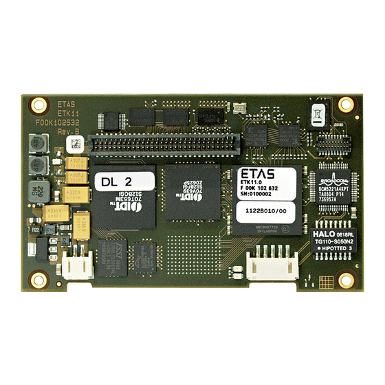
- Page 1 ETAS ETK11.0 Emulator Probe for Freescale MPC5500 Family User Guide...
- Page 2 The data in this document may not be altered or amended without special noti- fication from ETAS GmbH. ETAS GmbH undertakes no further obligation in relation to this document. The software described in it can only be used if the customer is in possession of a general license agreement or single license.
-
Page 3: Table Of Contents
Reset ..............27 ETK11.0 User Guide... - Page 4 ETAS Hardware ........
- Page 5 ETAS Contact Addresses ........
-
Page 6: About This Document
Presentation of Instructions The target to be achieved is defined in the heading. The necessary steps for this are in a step-by-step guide: Target definition 1. Step 1 2. Step 2 3. Step 3 > Result ETK11.0 User Guide... -
Page 7: Typographical Conventions
General emphasis and new terms are set in dimensional table of sample italics. points. Hardware Bold Menu commands, buttons, labels of the product Italic Emphasis on content and newly introduced terms Presentation of Supporting Information NOTE Contains additional supporting information. ETK11.0 User Guide... -
Page 8: Basic Safety Notices
Use of Open Source Software........14 Please observe the Product Safety Notices ("ETAS Safety Notice") and the fol- lowing safety notices to avoid health issues or damage to the device. - Page 9 Application Area of the Product This product was developed and approved for automotive applications. For use in other application areas, please contact your ETAS contact partner. Requirements for Operation The following requirements are necessary for safe operation of the product: •...
- Page 10 CAUTION Risk of short circuiting the internal signals of the ETK! When you mount the ETK to the ECU, you must ensure that the screws and washers used will not penetrate the ETK printed circuit board. ETK11.0 User Guide...
- Page 11 Cabling Use exclusively ETAS cables at the connections of the product! Adhere to the maximum permissible cable lengths! Observe the assignment of the cables to the connectors! Detailed information about cabling is located in the ETK User Guides.
-
Page 12: Identifications On The Product
Symbol for electrostatic sensitive components XETK-S14.0A Product designation (example) F 00K 110 722 Order number of the product (example) SN: yyxxxxx Serial number (7-digit) XXXX/YY Product version ZZZZ Year of manufacture ETAS GmbH, Manufacturer's address PO Box 300220, 70442 Stuttgart, Germany ETK11.0 User Guide... -
Page 13: Taking The Product Back And Recycling
2.6.1 CE Declaration of Conformity (European Union) With the CE mark attached to the product or its packaging, ETAS confirms that the product corresponds to the applicable product-specific European Direc- tives. The CE Declaration of Conformity for the product is available upon request. -
Page 14: China
7A and 7C-I in Annex III of this Directive. ETAS confirms that the product corresponds to this directive which is applica- ble in the European Union. -
Page 15: Introduction
Features ........... . . 15 Applications The ETK11.0 is an emulator test probe (ETK) for the Freescale MPC5500 microcontroller family with an external bus interface available. It is a typical par- allel ETK with a 16 bit interface. -
Page 16: Hardware Description
Reset ............27 Architecture Fig. 4-1 "ETK11.0 Architecture" shows the block diagram of the ETK11.0. The microcontroller can read and write from one of the two pages of the data emu- lation memory and can write its data directly to the measurement data mem- ory. -
Page 17: Microcontroller Interface
16 bit wide data bus and requires separate chip selects for the data emulation memory and the measurement memory. The data emulation mem- ory of the ETK11.0 is accessed by asserting the signal /SGCS of the ETK. The measurement memory is accessed by asserting the signal /SGWCS of the ETK. -
Page 18: Samtec Connector
Hardware Description Samtec Connector The Samtec connector is the interface between the ETK11.0 and the ECU. This connector has pins for the data bus, address bus, control signals, chip selects, boot configuration pins, ETK power connection, and grounds. For more detailed information of the 60 pin interface, refer to Chapter 7.10 "Signal... -
Page 19: Measurement Data Memory
The 128 Byte Trigger Segment, which is described in more detail in the section to follow, must be defined within the measurement data memory. For more information regarding the Display Table 13 process, please contact your local ETAS representative. ETK11.0 User Guide... -
Page 20: Triggering Of Measurement Data Acquisition
ECU is able to start different data acquisition tasks by writing differ- ent trigger addresses (trigger 1 to trigger 32). The ETK11.0 contains a trigger comparator which can be configured to select a segment of 128 Bytes out of the measurement data memory address space (at a 128 Byte boundary). -
Page 21: Fig. 4-6 Division Of The 128 Byte Trigger Segment
ETK_Disable ETK_Enable Fig. 4-6 Division of the 128 Byte Trigger Segment The ETK11.0 provides an extended trigger segment with up to 32 direct 16-bit hardware triggers. NOTE The unused address areas within the trigger segment are reserved for future applications and must not be used for other purposes. -
Page 22: Data Retention In Data Emulation And Measurement Data Memory
The content is random after a power failure of the ETK. If the ETK11.0 is used as a normal RAM, it may be useful that this copying pro- cedure is switched off. This can be done by any of the following: •... -
Page 23: Code Flash Memory
The most common approach to meet this requirement is to power the ETK11.0 directly from the car battery. The input voltage of the ETK11.0 may vary between 4.3 V and 18 V. In case of higher input voltages to the ETK, an additional voltage converter is required. -
Page 24: Serial Etk Interface
Hardware Description Serial ETK Interface The ETK11.0’s 100 Mbit/s serial interface, CON3, is the link to the ETAS calibra- tion and development system. The ES1232-A board for the ES1000 system, the ES690, the ES590, the ES591, and the ES910 will support this 100 Mbit/s inter- face. -
Page 25: Status Leds
ETAS Hardware Description Status LEDs There are three LEDs displaying the operating status of the ETK11.0 (Fig. 4-10 on page 25). Fig. 4-10 Status LEDs State Definition ETK11.0 is supplied with power and active (i.e. the ECU is switched on or the ETAS calibration and development sys- tem is connected and ready to communicate with the ETK11.0) -
Page 26: Braindead Flashing
SGRESOUT, SGBOOTCFG[1:0], and /SGRSTCFG. Also, /CS0 of the microcon- troller must be connected to either /SGCS or /SGWCS of the ETK11.0 and must not be used by any other memory device on the ECU. The ETK11.0 must also be configured to use /SGRESOUT to monitor the microcontroller’s reset status, see “Configuration Features”... -
Page 27: Reset
ETK11.0 senses the status of the microcontroller’s reset state to gen- erate a write protect signal for its memories. If the "ETK Configuration Tool" setting "Reset-out signal from ECU is used" is set to "Yes", the ETK11.0 will monitor the microcontroller’s reset state on the pin /SGRESOUT. Otherwise, the ETK11.0 will monitor the reset state on the pin /SGRES. -
Page 28: Installation
Connecting to the Power Supply ....... . 28 Connection to the ECU To directly mount the ETK11.0 to the ECU, a 60 pin Samtec socket is required. It is also possible to connect the ETK11.0 to the ECU using the ETAE10 flexible circuit adapter. -
Page 29: Permanent Power Supply Inside Ecu Available, Scenario 2
Fig. 5-4 Permanent Power Supply inside ECU not available 5.2.4 Isolated Power Supply inside ECU The ETK11.0 does not require a galvanically isolated power supply. For special applications ETAS offers the isolated power supply ETP2. ECU Connector Permanent Supply Isolated Power Supply... -
Page 30: Etk Configuration
If this parameter is entered correctly in the corresponding ECU description file, it guarantees that every time the calibration system is started, the ETK is checked for the appropriate configuration. If necessary, the ETK will be configured appropriately to the corresponding project. ETK11.0 User Guide... -
Page 31: Configuration Features
NOTE Do not use the ETK11.0 with INCA when the ETK is in any state other than "ETK mode initialized". Always reconfigure the ETK after is was used as RAM adaptor to ensure correct behavior with INCA. - Page 32 Selects from which memory the ECU boots. In all boot modes except Selected by ECU, the appropriate signals from the microcontroller must be connected to the following signals of the ETK11.0: SGBOOTCFG[1:0] and /SGRSTCFG. The default value is Selected by ECU. NOTE To select any Boot mode other than "Selected by ECU", the configuration item...
-
Page 33: Connection List
ETK11.0 ECU connector. SGA12 is the most significant and SGA31 is the least significant address line of the ETK. Each of the most significant 4 address lines of the ETK11.0 are configurable to be either the microcontroller’s address line or ground. The configuration of the address lines in the connection list must match the actual connection made at the ETK11.0 ECU connector. - Page 34 ETK Configuration Tool. The ETK signal names under the "ETK Hardware Name" column are the names of the ETK sig- nals that should be used in a hardware design when connecting the ETK to the microcontroller. ETK11.0 User Guide...
-
Page 35: Technical Data
Choose in Windows System Control Center / Device Manager / Network Adapter the used network adapter by double-click. Deactivate the "Allow the computer to turn off this device to save power" option in the "Power Manage- ment" register. Confirm your configuration. ETK11.0 User Guide... -
Page 36: Supported Software
0 °C to +50 °C/ - 18 °F to +122 °F Relative humidity (non-condensing) 0 to 95% Operating altitude max. 5000 m/ 16400 ft Contamination level Degree of protection Determined by installation in ECU Overvoltage category (AC mains supply) ETK11.0 User Guide... -
Page 37: Configuration
Operating Current I = 12 V; Batt Batt ECU on; T = 20 °C 1) The ETK11.0 implements reverse voltage protection in the same range and may be used only with central load dump protection. ECU Switched Power Monitoring Parameter Symbol... -
Page 38: Test Characteristics
: Delay of ECU reset through ETK with transferring the flash Reset2 present, transfer active, U will be switched on) Batt : max. delay of ECU reset through ETK Reset3 and U will be switched on) Batt ETK11.0 User Guide... -
Page 39: Electrical Characteristics
ECU Data bus configured for 3.3V at -9 mA load at -12 mA load at 9 mA load at 12 mA load Open Drain FET; I = 0.2 A Dmax at -8 mA load Samtec connector not considered; PCB 1pF/cm ETK11.0 User Guide... -
Page 40: Signal Description
Technical Data 7.10 Signal Description The ETK11.0 signal names and descriptions are defined in the same manner as the Freescale MPC5500 microcontroller family. I.e. MPC5554 signal D15 should be connected to ETK11.0 signal SGD15 and MPC5554 signal A31 should be connected to ETK11.0 signal SGA31. - Page 41 Reserved Input 1 /SGRSTCFG Reset Configuration /SGRESOUT Reset Output Sense (Optionally used when configured, by default /SGRES is used.) /ETKCON ETK Detection - 3.9K Pull Down on SGUBATT Permanent Power Supply to the ETK IP 59, 60 ETK11.0 User Guide...
-
Page 42: Switching Characteristics
ETAS Technical Data 7.11 Switching Characteristics The following diagrams show the read timing and write timing the ETK11.0 is capable of meeting. NOTE The timing is measured at a reference level of 1.5 V. Output signals are mea- sured with 10 pF to ground and 50 to 1.5 V. -
Page 43: Write Timing: Data Emulation And Measurement Data Dpr
Address valid before write enable becomes active Address valid before end of write Address valid after end of write Data valid before end of write Data valid after end of write Write enable pulse width Write cycle time ETK11.0 User Guide... -
Page 44: Mechanical Dimensions
ETAS Technical Data 7.12 Mechanical Dimensions The reference measure for all drawings is millimeters. 7.12.1 ETK11.0 Fig. 7-3 ETK11.0 Dimensions - Top View Dimension Millimeters Inches 94.0 3.701 89.0 3.504 39.5 1.555 .197 .118 51.0 2.008 54.0 2.126 14.0 .551 .106... -
Page 45: Fig. 7-5 Etk11.0 Dimensions - Pcb To Pcb
Millimeters Inches .228 NOTE The figure directly above displays the PCB to PCB distance when the ETK11.0 is mounted directly to the ECU. This dimension is only accurate when the ECU is using Samtec part number SFM-130-02-S-D . ETK11.0 User Guide... -
Page 46: Cables And Accessories
Millimeters Inches 12.50 0.492 400.00 15.748 160.00 6.299 19.00 0.748 NOTE Shield connected to ECU housing. SKINDICHT compact screwing; Manufacturer: Lapp; Description: SH7; Order-No.: 5200 0830 Nut for compact screwing; Manufacturer: Lapp; Description: SM7; Order-No.: 5200 3490 ETK11.0 User Guide... -
Page 47: Fig. 8-2 Interface Cable Ka54, Proposal 2 (Long Thread)
Shield connected to ECU housing. SKINTOP compact screwing; Manufacturer: Lapp; Description: MS-SC 11 ; Order- No.: 5311 2320 (long thread) or 5311 2220 (short thread) Nut for compact screwing; Manufacturer: Lapp; Description: SM-PE 11 ; Order- No.: 5210 3220 ETK11.0 User Guide... -
Page 48: Interface Cable Ka55
Strain relief on ECU cover necessary. Shield not connected to ECU housing. 8.1.3 Interface Cable CBAM200 Fig. 8-5 Interface Cable CBAM200-0m38 Millimeters Inches 380.00 14.96 30.00 1.18 NOTE Shield connected to ECU housing, allows for ECU housing flush mounting. ETK11.0 User Guide... -
Page 49: Power Supply Cables
Power Supply Cable ETV Millimeters Inches 190.00 7.480 8.2.2 Cable with Filtercoil ETV2 Fig. 8-7 Power Supply Cable with Filtercoil ETV2 Millimeters Inches 190.00 7.480 50.00 1.969 8.2.3 Cable K70 Fig. 8-8 Power Supply Cable K70 Millimeters Inches 2000 78.74 ETK11.0 User Guide... -
Page 50: Cable Ka50
ETAS Cables and Accessories 8.2.4 Cable KA50 Fig. 8-9 Power Supply Cable KA50 Millimeters Inches 7.87 1.97 8.2.5 Cable CBM200 Fig. 8-10 Power Supply Cable CBM200 Millimeters Inches 3.94 ETK11.0 User Guide... -
Page 51: Adapters
ETAE10 Flex-Foil ETK-ECU Adapter Millimeters Inches 113.1 4.451 60.2 2.370 .224 .220 NOTE The read and write timings defined in section 7.11 on page 42 are not guaran- teed when the ETAE10 is connected between the ECU and the ETK11.0. ETK11.0 User Guide... -
Page 52: Ordering Information
60 pin Samtec Connector (mates with ETK11.0) Adapters Type Order-No. Note ETAE10 F 00K 102 816 Cables Please contact your local ETAS representative for further cable information. 9.4.1 Interface Cables Type Order-No. Note KA54 F 00K 001 302 Delivery without PG cable gland (see Chapter 8.1.1... -
Page 53: Power Supply Cables
F 00K 900 052 Cable JST PH - JST PH (2fc- 3fc, 0M1) Power Supply Type Order-No. Note ETP1 F 00K 000 624 ETK power supply for 6 - 36 V DC input ETP2 F 00K 104 010 Power Supply Interface for ETK11.0 User Guide... -
Page 54: Etas Contact Addresses
Germany WWW: www.etas.com ETAS Subsidiaries and Technical Support For details of your local sales office as well as your local technical support team and product hotlines, take a look at the ETAS website: ETAS subsidiaries WWW: www.etas.com/en/ contact.php ETAS technical support WWW: www.etas.com/en/... -
Page 55: Figures
ETK11.0 Dimensions - PCB to PCB ........ -
Page 56: Index
European Union ....13 ETAS Contact Addresses ... . .54 ETK Configuration ....30 ETK Configuration Tool .
Need help?
Do you have a question about the ETK11.0 and is the answer not in the manual?
Questions and answers