Table of Contents
Advertisement
Quick Links
Advertisement
Table of Contents

Related Manuals for ETAS ES590


Summary of Contents for ETAS ES590
- Page 1 ES590 ETK, CAN and K-Line Module User’s Guide...
- Page 2 Copyright The data in this document may not be altered or amended without special notification from ETAS GmbH. ETAS GmbH undertakes no further obligation in relation to this document. The software described in it can only be used if the customer is in possession of a general license agreement or single license.
-
Page 3: Table Of Contents
Contents 1 Introduction ........... . . 5 System Requirements . - Page 4 6 ETAS Contact Addresses ........
-
Page 5: Introduction
Introduction The ES590 ETK, CAN and K-Line Module is a powerful calibration device which can be used universally for ECU calibration. The 10/100 MBit Ethernet inter- face to the host PC makes high data transfer rates possible between the ECU on the one hand and the calibration software on the other. - Page 6 ThermoScan, AD-Scan or Lambda Meter, can be connected using the serial measuring bus. This means the ES590 can be used for a wide range of measur- ing and calibration tasks. 6 - 3 S E R A U T...
-
Page 7: System Requirements
1.1.1 Hardware The ES590 requires a power supply of 6 to 32 V DC. For complete technical data of the ES590, refer to Section "Technical Data" on page 15. The connection to the host PC requires a free Ethernet interface with an RJ-45 socket. -
Page 8: About This Manual
About This Manual This manual describes the ES590 ETK, CAN and K-Line Module and its use as a calibration device. 1.2.1 Structure The "Operation" chapter contains a description of the ES590 module, a description of the control and measuring interfaces as well as instructions on how to use it. -
Page 9: Operation
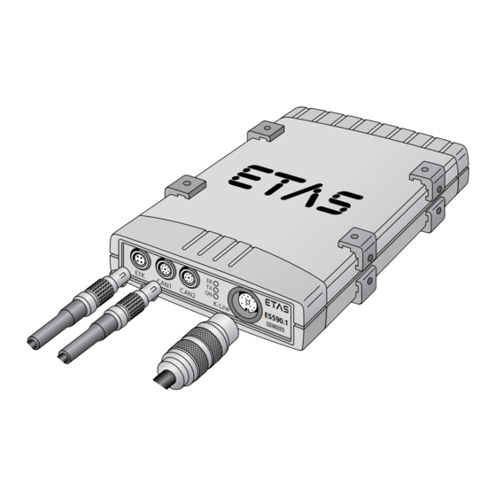
ETAS Product Catalog. Description of the Device The cable connections for the ECU interface of the ES590 are on the front of the device. In addition to the ETK interface, there are also two CAN interfaces and an interface for the K-Line. The LEDs indicating power supply, data trans- fer and error operation are also on the front of the device. -
Page 10: Leds
Switch off the device, switch it on again, and repeat the firmare update. If the error display still lights up, send the device back to ETAS Customer Service to be checked immediately. -
Page 11: Assembly
K-Line Calibration using the KWP2000 Keyword protocol and McMess are supported on the K-Line of the ES590. The serial interface of the ES590 can be used to connect one or several mea- suring devices via a serial measuring bus. Host The connection to the host PC is established at the host interface. - Page 12 The threads you use for fixing the ES590 are already available within the device and can easily be made accessible by removing the feet. To fix the ES590 housing: • Remove the plastic feet from the top and bottom of the device. To do this, first of all lift the foot from either the top or the bottom of the device and then carefully remove it from the housing.
-
Page 13: Cabling And Operation
Cabling and Operation The order in which you attach the cables to the interfaces of the ES590 is irrelevant. The interface cable for the host PC and the power supply cable for the ES590 are part of the standard delivery scope. You can order other cables in various lengths from ETAS. - Page 14 Automatic activation/deactivation of the device depends on the host PC. If a PC is connected and switched on, the ES590 is automatically switched on. Otherwise, the device remains in wait mode. The LED ON on the front of the device lights up when the device is switched on;...
-
Page 15: Technical Data
Technical Data Pin Assignment 3.1.1 ETK Interface Signal Signal Tx + Rx + Tx - Rx - 3.1.2 CAN Interface Signal Signal res. res. CAN low CAN GND CAN GND CAN high res. res. Technical Data... -
Page 16: K-Line
3.1.3 K-Line Signal Signal KL. 15 ECU GND res. ECU GND res. K-Line res. L-Line res. res. res. res. 3.1.4 SMB Interface Signal Signal res. n.c. n.c. n.c. res. n.c. Technical Data... -
Page 17: Host Interface
3.1.5 Host Interface Signal Signal res. Tx - res. Rx - res. res. Rx + Tx + General Data 3.2.1 Ambient Temperature Item Value Temperature range -40…+70 °C 3.2.2 Mechanical Data Item Value Dimensions (H/W/D) 36/126/160 mm Weight 600 g Protection class IP42 rated Technical Data... -
Page 18: Electrical Data
Electrical Data note All calibration interfaces (ETK, CAN, K-Line) and the PC interface are DC-decou- pled. 3.3.1 Power Supply Item Characteristics Value Operating voltage rev.-volt. protected 6…32 V Current consumption Continuous operation 500 mA at 12 V Wait mode 3 mA at 12 V 3.3.2 PC Interface Characteristics... -
Page 19: Can Interface
3.3.4 CAN Interface Characteristics Value Transfer rate (max.) 1 MBaud Format V2.0a, V2.0b Mode ISO high-speed or fault-tolerant 3.3.5 K-Line Characteristics Value Transfer rate (max.) 250 kBaud Mode K-/L-Line (ISO 9141-2) 3.3.6 Analog Output (Programming of the Flash EPROM in the ECU) Characteristics Value Output voltage... - Page 20 EN 61000-4-6 DIN EN 55022 B EN 60 529 EN 60 068-2-32 Technical Data...
-
Page 21: Cables And Accessories
Cables and Accessories note Only use ETAS cables at the interfaces of the ES590. The maximum admissible cable lengths must be adhered to. Ethernet Cable 4.1.1 Connecting Cable to the PC Side A Side B Fig. 4-1 CBE100-x Cable Product... -
Page 22: Connecting Cable To The Es600.1
4.1.2 Connecting Cable to the ES600.1 Straight Cable Side A Side B Fig. 4-2 CBE130-x Cable Product Length Order Number CBE130-0m4 0.4 m F 00K 102 748 CBE130-1 F 00K 102 588 CBE130-3 F 00K 102 587 CBE130-8 F 00K 102 586 Angled Cable Side A Side B... -
Page 23: Etk Interface Cable
ETK Interface Cable Side A Side B Fig. 4-4 CBM150-x Cable Product Length Order Number CBM150-3 F 00K 102 556 CBM150-5 F 00K 102 557 CBM150-10 10 m F 00K 102 553 CBM150-15 15 m F 00K 102 554 CBM150-20 20 m F 00K 102 555 CAN Interface Cable... -
Page 24: Cable K107
4.3.2 Cable K107 Side A Side B Side C Fig. 4-6 K107 Cable Product Length Order Number K107 F 00K 001 272 4.3.3 Cable CBAC150-2m5 Side A Side B Fig. 4-7 CBAC150-2m5 Cable Product Length Order Number CBAC150-2m5 2.5 m F 00K 104 159 Cables and Accessories... -
Page 25: K-Line Interface Cable
K-Line Interface Cable 4.4.1 Cable K96 Side A Side B Fig. 4-8 K96 Cable Product Length Order Number F 00K 000 383 4.4.2 Cable K78 Side A Side B Fig. 4-9 K78 Cable Product Length Order Number F 00K 000 579 Cables and Accessories... -
Page 26: Cable Adapter Ka45
4.4.3 Cable Adapter KA45 Side A Side B Fig. 4-10 KA45 Cable Adapter Product Length Order Number KA45 0,2 m F 00K 000 581 4.4.4 Cable Adapter K72 Side A Side B Fig. 4-11 K72 Cable Adapter Product Length Order Number 0.2 m F 00K 000 372 Cables and Accessories... -
Page 27: Cable Cback100-1M5
4.4.5 Cable CBACK100-1m5 Side A Side D Side B Side C Fig. 4-12 CBACK100-1m5 Cable Product Length Order Number CBACK100-1m5 1.5 m F 00K 104 160 SMB Interface Cable Side A Side B Fig. 4-13 K38 Cable Product Length Order Number F 00K Y 261 A24 342 Cables and Accessories... -
Page 28: Power Supply Cord
Power Supply Cord Side A Side B Side C Fig. 4-14 CBP120-2 Cable Product Length Order Number CBP120-2 F 00K 102 584 Cables and Accessories... -
Page 29: Ordering Information
Ordering Information ES590.1 Order Name Short Name Order Number ES590 Module, Cable ES590.1 F 00K 103 570 CBE100-3, Cable CBP120-2, User’s Guide (German and English) Accessories The following table contains a list of cables and adapters which are avail- able for the Module. - Page 30 Cable Length Short Name Order Number K-Line/CARB adapter 1.5 m CBAK100-1m5 F 00K 104 160 → CARB SMB interface Y 261 A24 342 Power supply CBP120-2 F 00K 102 584 Ordering Information...
-
Page 31: Etas Contact Addresses
Fax: +49 711 89661-105 Germany E-mail: sales@etas.de WWW: www.etasgroup.com North America ETAS Inc. 3021 Miller Road Phone: +1 888 ETAS INC Ann Arbor, MI 48103 Fax: +1 734 997-9449 E-mail: sales@etas.us WWW: www.etasgroup.com Japan ETAS K.K. Queen's Tower C-17F Phone:... - Page 32 Fax: +33 1 56 70 00 51 94588 Rungis Cedex E-mail: sales@etas.fr France WWW: www.etasgroup.com Korea ETAS Korea Co. Ltd. 4F, 705 Bldg. 70-5 Phone: +82 2 57 47-016 Yangjae-dong, Seocho-gu Fax: +82 2 57 47-120 Seoul 137-889 E-mail: sales@etas.co.kr Korea www.etasgroup.com...
-
Page 33: Index
Index Cables 21 Calibration software 7 Accessories 21 configuring the ES590 8 Activation/deactivation CAN interface automatic 10 formats 19 continuous operation 10 pin assignment 15 setting 14 protocols 11 Analog Output 19 Transfer rate 19 Applications 7 Configuring the ES590 8... - Page 34 10 update firmware 10 power supply (LED) 10 ES590 8 ON/AUTO ES6xx series 8 Switch 10 ETAS Contact Addresses 31 Operation 13 Ethernet topology 8 ETK Interface 18 ETK interface 7 PC Interface 18 Operating modes 10 PC interface 7...
- Page 35 Technical Data 15 data transfer (LED) 10 Wait mode see Activation/deactivation Contents...
Need help?
Do you have a question about the ES590 and is the answer not in the manual?
Questions and answers