Kyocera KM-3650W General Operations Manual
Kyocera km-3650w: user guide
Hide thumbs
Also See for KM-3650W:
- User manual (67 pages) ,
- Operation manual (50 pages) ,
- Quick reference (28 pages)

Related Manuals for Kyocera KM-3650W


Summary of Contents for Kyocera KM-3650W
- Page 1 KM-3650w General Operation Manual Please read the General Operation Manual before using this machine. Keep it close to the machine for easy reference.
-
Page 2: Table Of Contents
3. 1. 1. 5 Original Jam. Open the cover, and remove the original. 3. 1. 2 Open errors 3. 1. 2. 1 Cover is open. Close the Cover. or Printer is starting up. Page 1- 2 1- 3 1- 4... - Page 3 3. 1. 2. 3 Close the scanner cover. 3. 1. 3 Other messages 3. 1. 3. 1 Set XX roll paper to the Roll Deck. 3. 1. 3. 2 Set a paper to the bypass feeder. 3. 1. 3. 3 Toner empty.
-
Page 4: Chapter 1 Before Use
1. 1 Originals Prohibited from Duplication 1. 2 Features 1. 3 Specifications 1. 3. 1 General 1. 3. 2 Printer part 1. 3. 3 Scanner part 1. 4 Appearance 1. 4. 1 Front view 1. 4. 2 Rear view 1. 5 Specifications for the Scan Original 1. -
Page 5: Originals Prohibited From Duplication
Some kind of original is not allowed to copy. You may be punished by the law if only you possess the copy of some kind of original. We recommend you to consider enough before you copy such original. [Originals prohibited from copying by the law] 1. -
Page 6: Features
1. 2 Features (1) KM-3650w is a Multi-Function Printer which is available for scan, copy and print. (2) The operation speed is 60mm per second. (Metric) (Inch) 2.6ppm/E (3) The maximum print width is 914mm (36 inches) wide, and the minimum one is 279mm or 11”. -
Page 7: Specifications
Dimensions Weight Environmental condition for usage Interface Input power NOTE The above specifications may change without notice. Specification KM-3650w Console 1500W (Including Scanner, Controller Unit and every option) Idling Max. 54db Printing Max. 60db Impulse sound Max. 65db Max. 0.1ppm (Measurement method under UL Standard) 1525mm (Width) x 746mm (Depth) x 1230mm (Height) (Angle of Operation Panel is 45 degrees and trays are installed.) -
Page 8: Printer Part
1. 3. 2 Printer part Subject Printing method Photoreceptor Print speed Print head Resolution of print head Print width Print length Warm up time First print time Fusing method Development method Media Storage of consumables NOTE The above specifications may change without notice. -
Page 9: Scanner Part
1. 3. 3 Scanner part Subject Reading sensor Light source Scanning speed Setting of original Starting point of scan Scan width Scan length Margin area Optical resolution Digital resolution Original transportation Transportable original thickness NOTE The above specifications may change without notice. Specification Contact Image Sensor (CIS) (5 pieces of A4 sized CIS) -
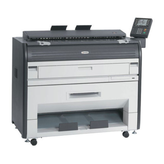
Page 10: Appearance
1. 4. 1 Front view Name Main Switch Original Guides Operation Panel Emergent Stop Button Original Tray Scanner Unit Toner Hatch (Original Table) Engine Unit Open Lever Bypass Feeder Roll Deck Print Tray Counter Function Turns on/off the machine. Guides the original to the Scanner Unit straight. Makes copy/scan operations. -
Page 11: Rear View
Inlet Socket Breaker Print Guide Trays Function Open the Exit Cover to access the paper jam. Connects the KM-3650w to the network. (Do not connect telephone line.) Turns on the Dehumidify Heater. Connect the Power Cord. Shuts off the AC power. -
Page 12: Specifications For The Scan Original
A scan original must satisfy the following specifications. Thickness 0.05mm to 0.6mm Width 279.4mm to 914.4mm (11” to 36”) Length 210mm to 3,600mm Do not scan the following kinds of original, because you may damage the original or scanner itself! Sticked with paste Torn Folded (Leading edge) - Page 13 Not square Wet image Made of metal or fabric Metal Fabric Patched Clipped or stapled Clipped Stapled 1-10 Chapter 1 Before Use...
- Page 14 Rough surface Rough surface (Carbon paper for example) Punched 1-11 Chapter 1 Before Use...
-
Page 15: Specifications For The Printing Paper
1. 6. 1 Papers not available to use Do not use the following kinds of printing paper because you may damage the print engine! So much curled paper Folded paper Creased paper Torn paper Punched paper 1-12 Chapter 1 Before Use... -
Page 16: Keeping The Paper In The Custody
Paper that has already been used for printing Very slippery paper Very sticky paper Very thin and soft paper OHP Film CAUTION Do not use the paper with staple, or do not use such conductive paper as aluminium foil and carbon paper. -
Page 17: Measures Against Environmental Condition
1. Turn on the Dehumidify Heater of the KM-3650w. 2. Remove the paper from the machine right after the completion of print, and keep it in a polyethylene bag. -
Page 18: Chapter 2 Basic Operations
2. 1 Turning on the Machine 2. 2 Turning off the Machine 2. 3 Replacement of Roll Paper 2. 4 Replacement of Toner Cartridge 2. 5 Set of Cut Sheet Paper to the Bypass Feeder 2. 6 Copying 2. 7 Emergent Stop of Scan or Copy 2. -
Page 19: Turning On The Machine
In U.S.A. : 120V, plus/minus 10%, 50/60Hz and 15A In Europe : 220-240V plus 6% or minus 10%, 50/60Hz and 10A 2. Press the Power Switch on the right side of the KM-3650w to turn on the machine. Power Switch 3. -
Page 20: Turning Off The Machine
2. 2 Turning off the Machine 1. Press the Power Switch on the right side of the KM-3650w to turn off the machine. Power Switch Press this side. CAUTION Do not unplug the KM-3650w for 1 minute after turning it off. -
Page 21: Replacement Of Roll Paper
Roll 2 is an optional part. The machine is equipped with the Roll 2 in the following instruction. NOTE Note that a paper jam tends to occur at the time of roll end. 1. Pull up the Lever (1) and draw out the Roll Deck (2). 2. - Page 22 the paper core. 4. Loosen the knob (5), slide the position of Paper Guide (6) according to the width of roll paper you will set, and then fix the Paper Guide (6) tightening the knob (5). NOTE Align the triangle mark (7) of the Paper Guide with each size guide (8).
- Page 23 NOTE (1) Be careful of the winding direction of roll paper at this time. (2) Try to rotate the Roll Spool after inserting to the roll paper to check whether or not it firmly holds the roll paper. Move up the Lever (4) if the paper is not held firmly.
- Page 24 feeding roller. Then rotate the Paper Feeding Knob (10) clockwise so that the feeding rollers catch the roll paper. NOTE In case of Roll 2, rotate the Paper Feeding Knob of rear side (11). 8. When the feeding rollers catch the paper, hold and pull the dent part (12) to the arrow direction to open the paper guide, and rotate the Paper Feeding Knob (10) until the leading edge comes out from the slit about 10cm.
- Page 25 another side to cut the leading edge. Remove the paper portion after cutting. NOTE Slide the Cutter Knob completely until stopped at the end, or a paper jam occurs. 10. Rewind the roll paper a little to place the leading edge as the following photo. 11.
-
Page 26: Replacement Of Toner Cartridge
2. 4 Replacement of Toner Cartridge 1. Open the Toner Hatch (Original Table) (1). 2. Slide the green Lever (2) to the right to unlock the Toner Cartridge. (Lever (2) is held automatically.) Chapter 2 Basic Operations... - Page 27 the body (4) of cartridge to the arrow direction some revolutions until it stops. (You can close the toner supplying hole of the cartridge firmly by this treatment.) NOTE The toner may drop from the toner supplying hole, and it may scattered into the machine or on the floor if you remove the Toner Cartridge without closing the toner supplying hole (5).
- Page 28 and right to make the toner smooth. 6. Pressing down the Cartridge Lock Lever (3), fit the pin (6) on the left side of cartridge to the groove (7) on the machine side. NOTE Confirm that the Cartridge Lock Lever (3) firmly locks the Toner Cartridge at the correct position.
- Page 29 7. Rotate the body (4) of the cartridge to the arrow direction some revolutions to open the toner supplying hole. (You may feel tight when rotating the body (4).) NOTE (1) Confirm that the projection (8) is fitted into the notch (9). (2) The Lever (2) may not lock the cartridge at this point of time, as it rotates and locks the cartridge automatically when Toner Hatch...
-
Page 30: Set Of Cut Sheet Paper To The Bypass Feeder
Feeder 1. Open the Bypass Feeder (1). 2. Put the cut sheet paper on the table along with the concerning size mark, and then insert it into the Bypass Feeder. When the paper touches the feeding roller, the machine automatically carries and sets the paper at the proper position. -
Page 31: Copying
1. Move the position of the Original Guides (1) according to the width of original. 2. Put the original on the Original Table with face up. Insert it under the Scanner Unit along with the original Guides. When the leading edge touches the original feeding roller, the machine automatically carries the original to scan its image. -
Page 32: Emergent Stop Of Scan Or Copy
Press the Emergent Stop Button (1) on the Scanner Unit if you will stop scanning or copying emergently in the middle. NOTE The original is stopped at the time you press the Emergent Stop Button. The printing paper is cut at the same time and it is ejected. 2-15 Chapter 2 Basic Operations... -
Page 33: Dehumidifying The Roll Paper (Option)
If the roll paper is humidified, it may cause several kinds of poor quality. Poor quality you will experience most will be “crease of paper” and “void of image”. Normal Print Normal Print Turn on the Dehumidify Heater if the room air is so humidified (higher than 65%) to prevent the above kinds of poor quality. -
Page 34: Chapter 3 Error Correction
Original Jam. Open the cover, and remove the original. 3. 1. 2 Open errors 3. 1. 2. 1 Cover is open. Close the Cover. or Printer is starting up. 3. 1. 2. 2 Roll Deck is open. Close the Roll Deck. 3. 1. 2. 3 Close the scanner cover. -
Page 35: Operator Call Errors
3. 1. 1 Paper jam When a paper jam occurred, any of the following messages will be displayed. • Paper jam in paper the Roll Deck. Set the roll paper correctly. • Paper jam in the bypass feeder. Remove the paper. •... - Page 36 the feeding roller. Rotate the Paper Feeding Knob (2) clockwise so that the feeding rollers catch the roll paper. NOTE (1) If the leading edge is extremely torn or folded, cut it off with a cutter or scissors. (2) Rotate the Paper Feeding Knob of rear side (3) for the Roll 2.
- Page 37 another side to cut the leading edge. Remove the paper portion after cutting. NOTE Slide the Cutter Knob completely until stopped at the end, or a paper jam occurs. 5. Rewind the roll paper a little to place the leading edge as the following photo. 6.
-
Page 38: Paper Jam In The Bypass Feeder. Remove The Paper
3. 1. 1. 2 Paper jam in the bypass feeder. Remove the paper. “Paper jam in the bypass feeder” is displayed when the cut sheet paper is mis-fed in the Bypass Feeder. 1. Pull up the Engine Unit Open Levers (1) to open the Engine Unit. 2. - Page 39 3. 1. 1. 3 Paper jam in internal area. Open the cover, and remove the paper. “Paper jam in internal area” is displayed when the paper is mis-fed in internal area of the machine. 1. Pull up the Engine Unit Open Levers (1) to open the Engine Unit. 2.
- Page 40 3. Close the Engine Unit firmly. NOTE Make sure to close the Engine Unit firmly until locked at the correct position. Chapter 3 Error Correction...
-
Page 41: Paper Jam In Exit Area. Open The Cover, And Remove The Paper
3. 1. 1. 4 Paper jam in exit area. Open the cover, and remove the paper. “Paper jam in exit area” is displayed when the paper is mis-fed in the exit area. 1. Pull up the Engine Unit Open Levers (1) to open the Engine Unit. Chapter 3 Error Correction... - Page 42 2. Check the position of the paper in the machine. If the paper is accessible from the front side as the right photo, go to the following procedure 3. If the paper is impossible to access from the front side because the end of paper is deep in the machine as the following photo, go to the following procedure 4.
- Page 43 Cover (3). 5. Remove the paper pulling to the rear side. WARNING Do not touch any part in the Exit Cover because some parts are extremely hot, or you will be burnt. Also be careful not to get burnt when you touch the printing paper as it may be very hot. NOTE Toner may be sticking on the Fuser Roller after removing the mis-fed paper.
-
Page 44: Original Jam. Open The Cover, And Remove The Original
3. 1. 1. 5 Original Jam. Open the cover, and remove the original. “Original jam” is displayed when the original is mis-fed in the Scanner Unit. 1. Open the Scanner Unit pulling up the Levers (1), and then remove the original. 2. -
Page 45: Open Errors
Open errors When any cover or unit of the machine is open, any of the following messages will be displayed. • Cover is opened. Close the Cover. or Printer is starting up. • Roll Deck is open. Close the Roll Deck. - Page 46 firmly. If not, close it firmly. NOTE The Toner Hatch (Original Table) may be opened slightly even if it looks closed firmly. 3. If the same error message is displayed although both Engine Unit and Toner Hatch (Original Table) are closed firmly, the machine is in the start up process. Wait for a while until the error message disappears automatically.
-
Page 47: Roll Deck Is Open. Close The Roll Deck
3. 1. 2. 2 Roll Deck is open. Close the Roll Deck. “Roll Deck is open” is displayed when the Roll Deck is open. 1. Check if the Roll Deck is closed firmly. If not, close it firmly. Roll Deck NOTE The Roll Deck may be opened slightly even if it looks closed firmly. -
Page 48: Close The Scanner Cover
3. 1. 2. 3 Close the scanner cover. “Close the scanner cover” is displayed when the Scanner Unit is open. 1. Check if the Scanner Unit is closed firmly. If not, close it firmly. NOTE The Scanner Unit may be opened slightly even if it looks closed firmly. -
Page 49: Other Messages
3. 1. 3 Other messages The following messages will be displayed according to the situation. • Set XX roll paper to the Roll Deck. • Set a paper to the bypass feeder. • Toner empty. Replace the toner cartridge. • In Warm Sleep Mode •... -
Page 50: Toner Empty. Replace The Toner Cartridge
Cartridge. 3. 1. 3. 4 In Warm Sleep Mode When “In Warm Sleep Mode.” is displayed, KM-3650w is in the Warm Sleep Mode to save the power consumption. Reference (1) The Warm Sleep Mode works automatically if you make no operation for the time specified in advance. -
Page 51: In Power Save Mode
3. 1. 3. 5 In Power Save Mode When “In Power Save Mode.” is displayed, KM-3650w is in the Power Save Mode to save the power consumption. Reference (1) The Power Save Mode works automatically if you make no operation for the time specified in advance. -
Page 52: Service Call Errors
You will note an error message “A significant error occurred. Call the service” on the operation panel if the machine has the fatal error. At this time one of the following sub messages is displayed also. Counter Error Cutter Error Developer Motor Error FPGA Error Fuser Low temp... - Page 53 4. 1 Cleaning of Each Part 4. 1. 1 Scanner Unit 4. 1. 2 Print Engine 4. 1. 3 Operation Panel Chapter 4 Maintenance Page 4- 2 4- 2 4- 4 4- 6 Chapter 4 Maintenance...
-
Page 54: Chapter 4 Maintenance
4. 1. 1 Scanner Unit Clean each Scan Glass, Feeding Rollers and Guide Plates once per a week, as the scan/copy image may become defective if these parts are dirty. 1. Confirm that the machine is turned off. 2. Open the Scanner Unit pulling up the Levers (1). 3. - Page 55 4. Wipe both the Upper Guide Plate (4) and the Lower Guide Plate (5) with a soft dry cloth. 5. Move the Scanner Unit a little to the rear side to unlock, and then close it. Chapter 4 Maintenance...
-
Page 56: Print Engine
4. 1. 2 Print Engine Clean each Guide Film and Guide Plate once per a week, as the toner or paper dust may accumulates on such part which may result in a defective print image. 1. Confirm that the machine is turned off. 2. - Page 57 NOTE (1) Photoconductive Drum (large green cylinder) right above the Guide Film. You need to replace the Drum if damaged, as it is a very important part in creating the print image. Be careful about the following matters. a.) Do not touch the drum. If you put your fingermark or oil on the Drum, it will cause for the defective image.
-
Page 58: Operation Panel
4. 1. 3 Operation Panel Clean the Operation Panel once per a week. 1. Confirm that the machine is turned off. 2. Wipe the Operation Panel with a dry cloth. NOTE Do not use water, alcohol, organic solvent and glass cleaner for the cleaning. Chapter 4 Maintenance... - Page 59 For best results and machine performance, we recommend that you use only our original supplies for your products.
- Page 61 ©2006 is a trademark of Kyocera Corporation...
- Page 62 2006.3 Rev.1.0...
Need help?
Do you have a question about the KM-3650W and is the answer not in the manual?
Questions and answers