Festo ELGA-BS-KF-70 ML Series Repair Instructions
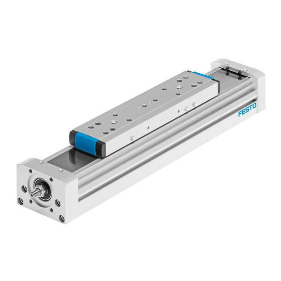
Spindle axis
Hide thumbs
Also See for ELGA-BS-KF-70 ML Series:
- Instructions (5 pages) ,
- Operating instructions manual (112 pages)
Table of Contents
Advertisement
Quick Links
Advertisement
Table of Contents

Related Manuals for Festo ELGA-BS-KF-70 ML Series


Summary of Contents for Festo ELGA-BS-KF-70 ML Series
- Page 1 Spindle axis ELGA-BS-KF-... Repair instructions (en) 7ELGA-BS-KFa_en...
- Page 2 Imprint Version: 7ELGA-BS-KFa_en (12.2017) Copyright: ©Festo AG & Co. KG Postfach 73726 Esslingen Germany Editorial team: Spare Part Documentation and Support Phone: +49 / 711 / 347-0 Fax: +49 / 711 / 347-2144 Email: service_international@festo.com Internet: http://www.festo.com Reproduction, distribution or sale of...
- Page 3 These repair instructions have been prepared with care. Festo AG & Co. KG does not, however, accept liability for any errors in these repair instructions or their consequences. Likewise, no liability is accepted for direct or consequential damage resulting from incorrect use of the products.
-
Page 4: Table Of Contents
4.4.2 Mounting the retainer or retainer module with spindle assembly on the slide module 4.4.3 Mounting the roller carriages 4.4.3.1 ELGA-BS-KF-70 / 80 4.4.3.2 ELGA-BS-KF-120 / 150 4.4.4 Relubricating the recirculating ball bearing guide 4.4.5 Assembling the spindle axis 4.4.6 Mounting the cover band 4 / 54 Festo 7ELGA-BS-KFa_en... - Page 5 4.6.2 Sticking on the new measuring tape Assembly and functional test No-load torque Start-up Cleaning Maintenance Check the reversing backlash Checking the cover band Relubricating the spindle axis Relubricating the roller carriage and spindle assembly Tools Standard tools Special tools Liability Festo 7ELGA-BS-KFa_en 5 / 54...
-
Page 6: Important Information
Spare parts documentation Contains an overview of the spare and wearing parts as well as information on their installation. This can be found in the online spare parts catalogue on the Festo website ( www.festo.com/spareparts). – Information brochure – accessories, equipment and tools Contains an overview of the available installation resources, e.g. -
Page 7: Text Designations Used In These Repair Instructions
Note the strength class of the screws, bolts and nuts! Festo recommends use of LOCTITE 243 thread locking agent. In the event of damage caused by unauthorised manipulation, improper use or use of non-original spare parts, all warranty and liability claims against the manufacturer expire. -
Page 8: Technical Requirements
Instead of carrying out the repair yourself, your local Festo sales office offers the option of having the repair carried out by Festo. Components and equipment replaced during repair must be disposed of in accordance with the relevant local environmental protection regulations. -
Page 9: General Product Description
Size Part number codes, technical data and dimensions of the ELGA-BS-KF ELGA-BS-KF-70-…-ML 8024918 spindle axes can be found in the product catalogue or on ELGA-BS-KF-80-…-ML 8024919 the Festo website ( www.festo.com). ELGA-BS-KF-100-…-ML 8024920 ELGA-BS-KF-150-…-ML 8024921 Festo 7ELGA-BS-KFa_en 9 / 54... -
Page 10: Slide Variants And Orientation Definition
8024919 HD13 4 Product Key ABCDEFG12345 5 Product Key Code Data Matrix Barcode (http://pk.festo.com/ + Product Key) The order code on the product labelling provides the following information: ELGA ELGA type spindle axis Ball screw Recirculating ball bearing guide Size... -
Page 11: Component Overviews And Bill Of Materials
The following diagrams are intended only to provide an overview of the individual components. To order spare and wearing parts, please use the online spare parts catalogue on the Festo website ( www.festo.com/spareparts). Festo 7ELGA-BS-KFa_en 11 / 54... -
Page 12: Elga-Bs-Kf-70
ELGA-BS-KF-70-…-ML components overview 12 / 52 Festo 7ELGA-BS-KFa_en... -
Page 13: Elga-Bs-Kf-70
Socket head screw, DIN 912-M4×45-8.8 Roller carriage O-ring, ISO 3601-B-1.5×1-N-NBR70 Lubricating channel Lubricating channel Socket head screw, DIN 912-M3×5-8.8 Lubricating head O-ring, 3×1-N-NBR70 Lubricating head module Clip Socket head screw, DIN 6912-M4×6-A2-70 End cap Belt reversal Festo 7ELGA-BS-KFa_en 13 / 52... -
Page 14: Elga-Bs-Kf-80
ELGA-BS-KF-80-…-ML components overview 14 / 52 Festo 7ELGA-BS-KFa_en... -
Page 15: Elga-Bs-Kf-80
Socket head screw, DIN 912-M5×45-10.9 Roller carriage O-ring, ISO 3601-B-1.5×1-N-NBR70 Lubricating channel Lubricating channel Socket head screw, DIN 912-M3×5-8.8 Lubricating head O-ring, 3×1-N-NBR70 Lubricating head module Clip Socket head screw, DIN 6912-M4×6-A2-70 End cap Belt reversal Festo 7ELGA-BS-KFa_en 15 / 52... -
Page 16: Elga-Bs-Kf-120
ELGA-BS-KF-120-…-ML components overview 16 / 52 Festo 7ELGA-BS-KFa_en... -
Page 17: Elga-Bs-Kf-120
Roller carriage Socket head screw, DIN 912-M5×20-10.9 Barbed L-fitting, LCN-M5-PK-2 Flange screw, F-M4×10-A-70 Fittings kit Clip Socket head screw, DIN 6912-M5×6-A2-70 End cap Belt reversal Slide module Centring sleeve, ZBH-9 Lubrication nipple, DIN 3405-AM 6 Festo 7ELGA-BS-KFa_en 17 / 52... -
Page 18: Elga-Bs-Kf-150
ELGA-BS-KF-150-…-ML components overview 18 / 52 Festo 7ELGA-BS-KFa_en... -
Page 19: Elga-Bs-Kf-150
Socket head screw, DIN 912-M8×118-10.9 Socket head screw, DIN 912-M6×20-10.9 Roller carriage Reducer, M6-M3-SW8 Barbed L-fitting, LCN-M3-PK-2-B Flange screw, F-M4×10-A-70 Fittings kit Clip Socket head screw, DIN 6912-M5×6-A2-70 End cap Belt reversal Centring sleeve, ZBH-9 Festo 7ELGA-BS-KFa_en 19 / 52... -
Page 20: Repair Steps
1. Disconnect the spindle axis from the power supply and secure it from being switched on again accidentally. 2. Remove the motor and encoder cables. 3. Dismantle the motor, axial kit or parallel kit. 20 / 54 Festo 7ELGA-BS-KFa_en... -
Page 21: Visual Inspection
The ELGA-BS-KF-70 / 80 has one compression spring mounted on each upper belt reversal. – The ELGA-BS-KF-120 / 150 has two compression springs mounted on each upper belt reversal. 4. Pull out the top belt reversals on both sides of the slide module. Festo 7ELGA-BS-KFa_en 21 / 54... -
Page 22: Removing The Bearing Cap, Bearing Block And Spindle Assembly With Slide Module
2. Carefully pull the bearing cap off the cylinder barrel. ELGA-BS-KF-70 3. Unscrew the hex nut from the spindle assembly. ELGA-BS-KF-80 / 120 / 150 3. Unscrew the slotted nut from the spindle assembly. 22 / 54 Festo 7ELGA-BS-KFa_en... -
Page 23: Disconnecting The Retainer Or Retainer Module With Spindle Assembly From The Slide Module
ELGA-BS-KF-70 / 80 Dismantling the roller carriage 1. Place the slide module with the mounted on spindle assembly on the work surface. The slide module faces upwards. 2. Unscrew the socket head screws from the roller carriage. Festo 7ELGA-BS-KFa_en 23 / 54... - Page 24 4. Pull off the roller carriages to the right and left and off the lubricating channels. 5. Remove the roller carriages. Dismantling the lubricating heads and lubricating channels 6. Unscrew the socket head screws from the lubricating heads. 7. Remove the lubricating heads. 24 / 54 Festo 7ELGA-BS-KFa_en...
- Page 25 12. Remove the spindle assembly with retainer or retainer module from the slide module. 13. Remove the O-rings from the slide module. 14. Clean the slide module. 15. Check the O-rings for wear and replace if necessary. Festo 7ELGA-BS-KFa_en 25 / 54...
-
Page 26: Elga-Bs-Kf-120 / 150
1. Place the spindle assembly on the work surface with the slide module facing downwards. 2. Unscrew the socket head screws from the roller carriage. 3. Unscrew the flange screws in the two barbed L-fittings of the lubrication. 4. Pull the cartridges out of the drill holes. 26 / 54 Festo 7ELGA-BS-KFa_en... - Page 27 8. Unscrew the four socket head screws for mounting the retainer module from the slide module. The figure on the right shows ELGA-BS-KF-150. 9. Remove the spindle assembly with the retainer module from the slide module. 10. Clean the slide module. Festo 7ELGA-BS-KFa_en 27 / 54...
-
Page 28: Replacing The Retainer Or Retainer Module
9. Wet the threaded hole with screw locking agent. 10. Screw in the socket head screw and tighten with the appropriate tightening torque. Size Number of socket head Tightening torque screws ELGA-BS-KF-70 2.5 Nm ELGA-BS-KF-80 5 Nm ELGA-BS-KF-120 3.5 Nm ELGA-BS-KF-150 7 Nm 28 / 54 Festo 7ELGA-BS-KFa_en... -
Page 29: Checking And Replacing The Roller Bearing And The Spindle Assembly
1. Drive the roller bearing out of the bearing block. Note Ensure that the seat of the roller bearing is not damaged when it is pulled off the spindle assembly. 2. Pull the roller bearing off the spindle assembly. Festo 7ELGA-BS-KFa_en 29 / 54... -
Page 30: Checking And Replacing The Deep-Groove Ball Bearing With Seat In The Bearing Cap
Ensure that the seat of the deep-groove ball bearing is not damaged when it is pulled off the spindle assembly. 2. Remove the retaining ring from the spindle assembly. 3. Pull the deep-groove ball bearing off the spindle assembly. 30 / 54 Festo 7ELGA-BS-KFa_en... -
Page 31: Checking And Replacing The Spindle Assembly
Chapter 4.3.5.2 on page 30). 3. Replace the retainer or retainer module ( Chapter 4.3.4 on page 28). 4. Mount the deep-groove ball bearing with seat in the bearing cap ( Chapter 4.3.5.2 on page 30). Festo 7ELGA-BS-KFa_en 31 / 54... -
Page 32: Mounting The Spindle Axis
Festo LUB-KC1 Chapter 7.4 on page 51 For further information, refer to the information brochure: “Accessories, equipment and tools”. The brochure can be found in the online spare parts catalogue on the Festo website ( http://spareparts.festo.com/xdki/data/SPC/0/PDF_SAFE/Fitting%20aids.pdf 4.4.2 Mounting the retainer or retainer module with spindle assembly on the slide module Requirement The spindle assembly is mounted in the retainer or in the retainer module (... - Page 33 When assembling, press the entire contact area of the retainer assembly onto the stop edge of the slide module. The stop edge of the slide module is located on the side with the lubrication nipples. Festo 7ELGA-BS-KFa_en 33 / 54...
-
Page 34: Mounting The Roller Carriages
Chapter 4.4.2 on page 32). The new roller carriages are supplied as follows: – for ELGA-BS-KF-70 / 80 in pairs on an assembly tool, – for ELGA-BS-KF-120 / 150 individually, each on an assembly tool. 34 / 54 Festo 7ELGA-BS-KFa_en... -
Page 35: Elga-Bs-Kf-70 / 80
9. Press the lubricating heads onto the stop face. 10. Screw in the socket head screws and tighten with the appropriate tightening torque. Size Tightening torque ELGA-BS-KF-70 1.5 Nm ELGA-BS-KF-80 1.5 Nm 11. Push the O-rings right and left onto the lubricating channels. Festo 7ELGA-BS-KFa_en 35 / 54... - Page 36 Size Tightening torque ELGA-BS-KF-70 1.5 Nm ELGA-BS-KF-80 1.5 Nm 19. Use compressed air and a cloth to clean the cylinder barrel and roller track. 36 / 54 Festo 7ELGA-BS-KFa_en...
-
Page 37: Elga-Bs-Kf-120 / 150
Note the alignment of the roller carriage 2 on assembling! The ground sides of the roller carriage 4 must be installed facing the stop edge 1 of the slide module 3. Festo 7ELGA-BS-KFa_en 37 / 54... - Page 38 4. Push the roller carriage to the end of the assembly aid, far enough to allow the adapter to be mounted in the thread that has become free. 5. Screw the adapter into the roller carriage and tighten with the appropriate tightening torque. Size Tightening torque ELGA-BS-KF-150 0.5 Nm 38 / 54 Festo 7ELGA-BS-KFa_en...
- Page 39 The ground side of the roller carriage must touch the stop edge of the slide. 14. Push the cartridges onto the free ends of the plastic hoses. 15. Screw in the socket head screws loosely. Festo 7ELGA-BS-KFa_en 39 / 54...
- Page 40 New roller carriages must be lubricated before commissioning the spindle axis ( Chapter 4.4.4 on page 41). Non-compliance can lead to unlubricated operation, and thus failure of the spindle axis before the next specified relubrication. 40 / 54 Festo 7ELGA-BS-KFa_en...
-
Page 41: Relubricating The Recirculating Ball Bearing Guide
The recirculating ball bearing guides must be lubricated with a grease gun before commissioning and at certain intervals ( Chapter 7.4 on page 51). Festo offers a one-hand high-pressure grease gun with a suitable pinpoint nozzle for greasing the lubricating holes ( Chapter 8.2 on page 52). - Page 42 16. Push the slide module in the direction of the bearing cap until it stops. 17. Tighten the socket head screws using the appropriate torque. Size Tightening torque ELGA-BS-KF-70 2.5 Nm ELGA-BS-KF-80 5 Nm ELGA-BS-KF-120 12 Nm ELGA-BS-KF-150 20 Nm 42 / 54 Festo 7ELGA-BS-KFa_en...
-
Page 43: Mounting The Cover Band
8. Wet the two grub screws with locking agent. 9. Screw the grub screws into the bearing cap and tighten with the appropriate tightening torque (see Table). Size Tightening torque ELGA-BS-KF-70 2.0 Nm ELGA-BS-KF-80 2.0 Nm ELGA-BS-KF-120 2.0 Nm ELGA-BS-KF-150 2.0 Nm Festo 7ELGA-BS-KFa_en 43 / 54... -
Page 44: Replacing The Buffers Or Buffer Elements
These buffers and buffer elements can be replaced at any time without dismantling the spindle axis. 1. Use pliers to pull out the buffers or buffer elements. 2. Replace the buffers or buffer elements in the bearing block and in the bearing cap. 44 / 54 Festo 7ELGA-BS-KFa_en... -
Page 45: Elga-Bs-Kf-150 Only - Replacing The Buffers In The Slide Module
4. Use pliers to pull out the buffers. 5. Replace the buffers in the roller carriage. 6. Re-assemble the spindle axis ( Chapter 4.4.5 on page 41). 7. Mount the cover band ( Chapter 4.4.6 on page 43). Festo 7ELGA-BS-KFa_en 45 / 54... -
Page 46: Replacing The Measuring Tape Of The Incremental Displacement Encoder
4. Remove the measuring tape carefully from the cylinder barrel, do not use any sharp-edged auxiliary means. 5. Clean the cylinder barrel to remove adhesive residues. Festo recommends LOCTITE 7063 and LOCTITE 7070 for cleaning. 4.6.2 Sticking on the new measuring tape... - Page 47 9. Wet the countersunk screws with locking agent. 10. Screw countersunk screws through the caps and into the slot nuts and tighten with a tightening torque of 0.15 Nm. Festo 7ELGA-BS-KFa_en 47 / 54...
- Page 48 The deviation in the parallelism between the measuring unit 2 and the magnetic strip 1 must not exceed ±5°. – The deviation in the parallelism between the measuring unit 2 and the magnetic strip 1 must not exceed ± 1.5°. 48 / 54 Festo 7ELGA-BS-KFa_en...
-
Page 49: Assembly And Functional Test
This check is based on the technician’s instinct and experience. It is not possible to specify precise test values. Start-up Commission the repaired spindle axis as described in the operating instructions (enclosed with the spindle axis or available on the Festo website ( www.festo.com)). Festo 7ELGA-BS-KFa_en 49 / 54... -
Page 50: Cleaning
When using other cleaning products, ensure that they do not corrode the non-metal parts of the linear drive. If in doubt, check the resistance of the non-metal parts with the help of the information on the Festo website ( www.festo.com). -
Page 51: Relubricating The Roller Carriage And Spindle Assembly
2.0 g 2.5 g 3.0 g 15 g in lubrication nipple 2 Festo offers a one-hand, high-pressure grease gun with a suitable pointed nozzle for greasing the lubrication nipples ( Chapter 8.2 on page 52). Festo 7ELGA-BS-KFa_en 51 / 54... -
Page 52: Tools
Sturdy general purpose scissors or metal shears Special tools The following special tools are required for repair and maintenance of the spindle axis: Designation Additional information Festo order no. Figure One-hand grease gun LUB-1 Pinpoint nozzle for 647958 miniature, funnel-shaped... -
Page 53: Liability
The brochure can be found in the online spare parts catalogue on the Festo website ( http://spareparts.festo.com/xdki/data/SPC/0/PDF_SAFE/Fitting%20aids.pdf Liability The general terms and conditions of business (Allgemeinen Geschäftsbedingungen - AGB) of Festo AG & Co. KG apply; these can be read on the Festo website ( www.festo.com). Festo 7ELGA-BS-KFa_en 53 / 54... - Page 54 Festo provides both documentation. In the case that electronic Example: E 2003, Festo AG & Co. KG, on portable data storage devices (diskettes, documentation in the form of data storage D-73726 Esslingen...
Need help?
Do you have a question about the ELGA-BS-KF-70 ML Series and is the answer not in the manual?
Questions and answers