
Subscribe to Our Youtube Channel
Related Manuals for HMS Networks Anybus


Summary of Contents for HMS Networks Anybus
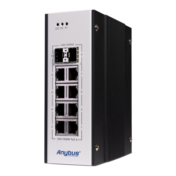
- Page 1 ENGLISH ® Anybus Managed Layer 2 PoE Switch STARTUP GUIDE SP2978 Version 1.1 Publication date 2022-05-09...
- Page 2 The information in this document shall therefore not be construed as a commitment on the part of HMS Networks and is subject to change without notice. HMS Networks makes no commitment to update or keep current the information in this document.
-
Page 3: About This Document
Managed Layer 2 PoE Switch 1. Preface 1.1. About This Document ® This document describes how to install Anybus Managed Layer 2 PoE Switch. For additional documentation and software downloads, FAQs, troubleshooting guides and technical support, please visit www.anybus.com/support. 1.2. Document Conventions... - Page 4 Additional information which may facilitate installation and/or operation. Helpful advice and suggestions. 1.3. Trademarks ® Anybus is a registered trademark of HMS Networks. All other trademarks are the property of their respective holders. Page 2 of 16 SP2978 Version 1.1...
-
Page 5: Intended Use
® Safety Anybus Managed Layer 2 PoE Switch 2. Safety 2.1. Intended Use The intended use of this equipment is as a communication interface and gateway. The equipment receives and transmits data on various physical levels and connection types. If this equipment is used in a manner not specified by the manufacturer, the protection provided by the equipment may be impaired. - Page 6 ® Anybus Managed Layer 2 PoE Switch General Safety CAUTION This equipment is recommended for use in both industrial and domestic environments. For industrial environments it is mandatory to use the functional earth connection to comply with immunity requirements. For domestic environments the functional earth must be used if a shielded Ethernet cable is used, in order to meet emission requirements.
- Page 7 ® General Safety Anybus Managed Layer 2 PoE Switch IMPORTANT Installation, configuration, putting into service, use and maintenance must be performed by personnel authorized by the manufacturer. IMPORTANT Using the wrong type of power supply can damage the equipment. Ensure that the power supply is connected properly and of the recommended type.
- Page 8 ® Anybus Managed Layer 2 PoE Switch Cyber Security 3. Cyber Security IMPORTANT The equipment is intended to be used in a restricted access location. Access should only be given to skilled person or instructed person who has been instructed in the operation of the equipment.
-
Page 9: Package Checklist
Safety and Regulatory Compliance Information 4.2. Support and Resources For additional documentation and software downloads, FAQs, troubleshooting guides and technical support, please visit www.anybus.com/support. NOTE Have the product article number available, to search for the specific product page. You find the product article number on the product cover. -
Page 10: Installation
® Anybus Managed Layer 2 PoE Switch Installation 5. Installation 5.1. DIN Rail Mounting NOTE Mount the switch on a DIN rail in accordance with the EN 50022 standard. NOTE Mount the switch at a height of ≤2 m. Mount the switch on a DIN rail: 1. - Page 11 ® Connecting Ground Screw Anybus Managed Layer 2 PoE Switch 5.2. Connecting Ground Screw CAUTION To avoid system damage, the equipment should be connected to ground. Figure 1. Grounding Screw Establish a direct connection between the ground screw and the grounding surface prior to connecting devices.
- Page 12 ® Anybus Managed Layer 2 PoE Switch Connecting Digital Output Wires 5.3. Connecting Digital Output Wires The relay output of the 2-pin terminal block connector are used to detect user-configured events. When a user-configured event is triggered, the two wires attached to the fault contacts, form a close circuit.
-
Page 13: Connecting To Ethernet
® Connecting Digital Input Wires Anybus Managed Layer 2 PoE Switch 5.4. Connecting Digital Input Wires The Digital Input comes with photo-coupler isolation. NOTE The Digital High accepts 11 - 30 VDC. The Digital Low accepts 0 - 10 VDC. - Page 14 ® Anybus Managed Layer 2 PoE Switch Connecting Power Wires 5.7. Connecting Power Wires CAUTION Ensure that the power supply is turned off before connecting it to the equipment. CAUTION When wiring low voltage input for Managed L2 PoE Switch output, it may generate higher current.
- Page 15 ® Diagnostic Console and Reset Button Anybus Managed Layer 2 PoE Switch 5.8. Diagnostic Console and Reset Button The switch provides a reset button and a diagnostic console connector. For the RS232 Diagnostic Console, the default baud rate settings are 115,200, N, 8, 1.
-
Page 16: Before You Begin Configuration
® Anybus Managed Layer 2 PoE Switch Configuration 6. Configuration 6.1. Before You Begin Configuration The switch is configured through web management. You can also configure the switch through console management, Telnet management or SSH management. NOTE The switch default IP address is http://192.168.10.1/. -
Page 17: Verify Operation
® Verify Operation Anybus Managed Layer 2 PoE Switch 7. Verify Operation Table 2. System LED Indicators Status Description P1 and P2 Power Green DC-IN power is on No power in DC-IN DO/Alarm Failure in port link, ping, power, DO or DI State by SW control Operation normal Table 3. -
Page 18: Technical Data
Network Management IPv4 management, SNMP v1/v2c/v3/Trap, MIBs, LLDP, DHCP client, TFTP, System Log, NTP IEEE 802.3at Power Over Ethernet Plus (PoE+), backward compatible with 802.3af PoE For more information, refer to datasheet at www.anybus.com/support. Page 16 of 16 SP2978 Version 1.1...
Need help?
Do you have a question about the Anybus and is the answer not in the manual?
Questions and answers