Table of Contents
Advertisement
Quick Links
[8]
[1]
[2]
[3]
[1] Trigger inputs A-F & tamper wiring
[2] Trigger inputs G-H, power & outputs
[3] GSM module sockets
[4] Telephone line connector
[5] Back tamper switch
[6] Line connector
[7] Sounder/loudspeaker
[8] Microphone
This product complies with the requirements of European Directive:
1995/5/EC (Radio &Telecommunications Terminal Equipment Directive).
For more information and declarations of conformity please consult
www.security.co.uk
[7]
[6]
[5]
A
B
A1 B1
B1
[4]
© Cooper Security Ltd. 2009
Part Number 11947691 Issue 1
Cooper Security Ltd.
Security House
Vantage Point Business Village
Mitcheldean
Gloucestershire
GL17 0SZ
www.coopersecurity.co.uk
Product Support (UK) Tel:
+44 (0) 1594 541979.
08:15-12:30 and 13:00-17:00 Monday to Friday.
Product Support Fax: (01594) 545401
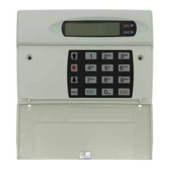
SD3 & GSM module
Quick Start Guide
OP1
SD3 +24°C
12:01 06Jul06
OP2
1
2
3
abc
def
4
5
6
ghi
jkl
mno
7
8
9
pqrs
tuv
wxyz
0
ENT
ESC
Clear
www.coopersecurity.co.uk
Advertisement
Table of Contents

Related Manuals for Cooper Security SD3


Summary of Contents for Cooper Security SD3
- Page 1 SD3 & GSM module Quick Start Guide SD3 +24°C 12:01 06Jul06 A1 B1 pqrs wxyz [1] Trigger inputs A-F & tamper wiring [2] Trigger inputs G-H, power & outputs Clear [3] GSM module sockets [4] Telephone line connector [5] Back tamper switch...
- Page 2 Before opening code (1234 as standard) (iii) Negative, normally open loop, (iv) Negative, normally closed loop. 2 Use & to display a the SD3 menu option. OP1 - OP4 disconnect all Four programmable switched negative 3 Press to select. power! @100mA outputs.
Need help?
Do you have a question about the SD3 and is the answer not in the manual?
Questions and answers