
Subscribe to Our Youtube Channel
Related Manuals for Cooper Security SD3

Summary of Contents for Cooper Security SD3
- Page 1 SD3 Speech Dialler Installation Guide GSM +24°C 12:00 01Jan13 pqrs wxyz Clear Issue 2 Page i...
-
Page 2: Table Of Contents
Contents Introduction......1 General ..........1 Specifications ........2 Connection Types And Standards ..2 Keys And Displays ....... 3 PCB Connectors And Switches ....3 Control Panel (SELV) Connections..4 +12V & 0V ........4 Trigger Inputs (A To H) ...... 4 Tamper .......... -
Page 3: Introduction
12V and power supply and battery backup) or 28V, with a supply capability of 200mA use the SD3 in a standalone role. or greater. This Guide shows you how to physically The speech dialler has a built-in GSM... -
Page 4: Specifications
Specifications Connection Types And Supply voltage: 12 - 28VDC Standards Current 50mA (Standby), All connections on the speech dialler consumption 170mA (Active) are Safety Extra Low Voltage or SELV (@12VDC): (SELV). Trigger Inputs: Eight: The PSTN module contains a mixture of positive/negative alarm system-related connections and applied or... -
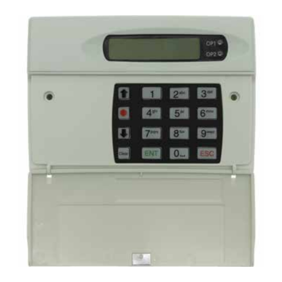
Page 5: Keys And Displays
Keys And Displays 1. Two-line backlit LCD display 2. Keypad 3. Red indicator shows the status of Output 1 GSM +24°C 12:00 01Jan13 4. Green indicator shows the status of Output 2 Keypad function keys pqrs wxyz Scroll up Clear Record / special character key Scroll down... -
Page 6: Control Panel (Selv) Connections
Trigger input connections for Control Panel (SELV) negative operation Connections Before making any connection to the speech dialler isolate ALL power from the control panel (mains and battery). Do not continue if there is power still present on the control panel. +12V &... -
Page 7: Installation
the speech dialler should be able to Installation work on that network. NOTE: When testing the signal Before installing the speech dialler, strength you must hold your phone please consider the type of network in the exact location of the speech account and the physical location of the dialler antenna. -
Page 8: Dealing With Poor Signal Strength
registered, the speech dialler will you have fitted the SIM card in the report the strength of the strongest correct orientation. network signal. This may be an emergency network. (In the UK, all networks must provide access to any mobile phone for emergency calls.) Check that the unit is registered before checking the signal strength. -
Page 9: Pstn Module Installation
PSTN module within the speech dialler. To program the speech dialler to use the PSTN module, please see the SD3 Programming Guide. CAUTION: Remove all power from the speech dialler before attempting to fit the PSTN module. - Page 10 board. Also ensure that the tamper spring from the speech dialler can pass freely through the hole provided in the PSTN module. 7 Connect the telephone cable to the telephone cable terminals (TNV) on the PSTN module. The easiest way to connect the PSTN Module to the telephone line is to use the telephone lead that is provided with the unit as shown below...
-
Page 11: Commissioning
¬¦ Ent to Select Commissioning [ENT] or [ESC] When beginning a new installation, it is 3 Use the scroll keys to select advisable to prompt the speech dialler the language you want to use. to make a factory reset in order to 4 Press to select. -
Page 12: To Register Your Sim Card
G S M (This may not appear if Press [ENT] N u m b e r you are using Vodafone To Leave Menus as a service provider.) Note this number down 2 Press to leave the programming so that you can supply it menu and return to standby. -
Page 13: Orange
Orange Using Top Up Cards Make sure you have the speech dialler’s Various service providers supply top up IMEI number to hand. You will also cards with their SIMs. Part of the need the SIM card serial number which registration procedure is to link the top is printed on the SIM card. -
Page 14: Programming Options List
Programming Options List Contact Details Alarm Levels Contact 01 Name Temperature High Contact 02 Name Temperature Low … Supply Low Contact 10 Name Signal Low Record Options Messages Long Play Voice Message Auto Record Voice Alarm A … Report Options Voice Alarm H Auto Reporting Voice Restore A... - Page 15 Clear by Options View Log Anyone for newer, for older) No One Test Options Outputs Test Messages Output 1 Send Alarm A To … Message Waiting Send Alarm H To Remote Access Send Restore A To Temperature High … Temperature Low Send Restore H To Listen Active Test Outputs...
- Page 16 © Cooper Security Ltd. Aug 2013 This product complies with the 1995/5/EC R&TTE Directive. For further details, please see: www.coopersecurity.co.uk Part Number 12362152 29/4/13 Page 14...
Need help?
Do you have a question about the SD3 and is the answer not in the manual?
Questions and answers