
Related Manuals for Kramer SG-6005


Summary of Contents for Kramer SG-6005
- Page 1 KRAMER ELECTRONICS, Ltd. USER MANUAL Kramer Genlock Multistandard Black Burst/Bar Generator Model: SG-6005 IMPORTANT: Before proceeding, please read paragraph entitled "Unpacking and Contents"...
-
Page 2: Table Of Contents
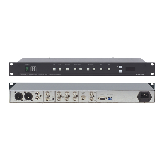
SG-6005 Front Panel Features SG-6005 Rear Panel Features RS-232 Null Modem Connection Table Instruction Set for the SG-6005 Front Panel Switches on the SG-6005 as defined in protocol KRAMER ELECTRONICS LTD. Table Of Contents List Of Illustrations List Of Tables... -
Page 3: Introduction
In addition to the unit you have just purchased, Kramer also offers a full line of high quality distributors, switchers, processors, interfaces, controllers and computer-related products. -
Page 4: Sync Location
Retrieving the sync information when embedded in the digital signal involves complicated circuitry and the problems related to digital syncs will not be discussed here. KRAMER ELECTRONICS LTD. -
Page 5: Some Common Problems
(2.8 Volts divided in 16.6) which is lower than acceptable. There’s no need to describe what will happen to the analog signal! Another catch – what if the horizontal sync is negative and the vertical sync is positive and they are translated into an analog signal? KRAMER ELECTRONICS LTD. -
Page 6: Solutions
The receiving end of the switched sources does not need to resynchronize its circuitry to the newly switched source, resynchronization does not take place and the transition is smooth. KRAMER ELECTRONICS LTD. -
Page 7: Factors Affecting Quality Of Results
48.3(W) x 17.8(D) x 4.5(H) cm. / 19 inch (W), 7 inch (D), 1U (H) rack mountable DIMENSIONS 2.5 Kg. (5.5 Lbs.) Approx. WEIGHT 230 VAC, 50/60 Hz, (115VAC, U.S.A.) 10 VA. POWER SOURCE KRAMER ELECTRONICS LTD. SG-6005 outputs on XLRs, 2x 1kHz, 1Vpp/100 outputs, on RCAs. -
Page 8: How Do I Get Started
UNPACKING AND CONTENTS The items contained in your Kramer Black Burst Generator package are listed below. Please save the original box and packaging materials for possible future shipment. -
Page 9: Getting To Know Your Sg-6005 Generator
The SG-6005 may be RS-232 controlled from a PC, and firmware is easily upgraded using a computer. The required SCH/Phase shifts and delay may be displayed on a large seven-segment LED display. The number of outputs may be increased by using a Kramer video distribution amplifier like the VM-1010, VM-1015, or VM- 1021, etc. - Page 10 When this function is not selected, the machine will still generate the previously selected bar. The selection allows display and selecting of this function, not the enabling and disabling of it. The bars which may be generated at the “COLOR BAR” output (19) are: KRAMER ELECTRONICS LTD.
-
Page 11: Rear Panel Features Description
A 1kHz, 1V p-p audio signal (sine wave) is generated on this pair of RCA outputs. (16) REF-IN AND LOOP INPUTS The bottom BNC is the reference input for genlocking the SG-6005. The top BNC may be used for looping the genlocking source. When looping, the 75 terminate the line by pressing in the 75 termination switch (17). -
Page 12: Resetting The Sg-6005
RESETTING THE SG-6005 The SG-6005 has non-volatile memory so that the machine will turn on to the state in which it was prior to being shut down. That is, changes made via the front-panel and via RS-232 will be “remembered” even after the machine is turned off. -
Page 13: Structure Of Protocol
The destination bit, TO PC, is 0 when sending from the PC to the machine, or 1 when sending from the machine to the The address bit, A0, is determined by the setting of DIP-switch 4 on the SG-6005. If the switch is in the ON position, ADDR should be set as 1;... -
Page 14: Description Of Instructions
Read EEPROM data Error Enable “Power-down save” Identify machine Table 1: Instruction Set for the SG-6005 DESCRIPTION OF INSTRUCTIONS INSTRUCTION 0 – RESET DATA=0: initialize the machine. When the machine is initialized, it will send the RESET code (DATA = 0). If the machine receives this code, it will reset to its “power-up”... - Page 15 If the machine receives an invalid instruction, it replies by sending this error code. INSTRUCTION 57 – ENABLE “POWER-DOWN SAVE” DATA = 0 disables power-down saving; DATA = 1 enables saving. EXTENDED DATA - set to 0. KRAMER ELECTRONICS LTD.
-
Page 16: Front Panel Switches On The Sg-6005 As Defined In Protocol
EXTENDED DATA is the value following the decimal point. For example, for version 3.4, the machine replies with DATA = 03 (hex), and EXTENDED DATA = 04 (hex). The table below shows the front-panel switch numbers, as defined for this protocol: Table 2: Front-Panel Switches on the SG-6005 KRAMER ELECTRONICS LTD. SWITCH... -
Page 17: Relationship Between "Switched Data" And Display
Connecting to Video and Audio Devices Video acceptors and output devices may be connected to the SG-6005 through the BNC type connectors on the back of the machines (Black Burst / Color Bar). The Black Burst and Color Bar signals are very high frequency carrying signals, and are very sensitive to cable quality and length. -
Page 18: Connecting To Horizontal And Vertical Sync Acceptors
Connecting to a PC Connect the PC COM port to the provided Null Modem adapter. Connect the Null modem adapter to the RS- 232 port of the SG-6005 using a flat cable with the appropriate sockets. TURNING ON THE MACHINE The machine should only be turned on after all connections are completed and all source devices have been turned on. -
Page 19: Rs-232 Null Modem Connection
Figure 3: RS-232 Null Modem Connection KRAMER ELECTRONICS LTD. -
Page 20: Taking Care Of Your Machine
If not, disconnect power from the machine and reconnect again to reset the machine. If the following recommended actions still do not result in satisfactory operation, please consult your KRAMER Dealer. Power and Indicators Problem No Power Confirm that the rocker switch is in the “ON”... -
Page 21: Limited Warranty
Any product which is not distributed by Kramer or which is not purchased from an authorized Kramer dealer. If you are uncertain as to whether a dealer is authorized, please contact Kramer at one of the agents listed in the web site www.kramerelectronics.com. - Page 22 HOW YOU CAN GET WARRANTY SERVICE To obtain service on you product, you must take or ship it prepaid to any authorized Kramer service center. Whenever warranty service is required, the original dated invoice (or a copy) must be presented as proof of warranty coverage, and should be included in any shipment of the product.
- Page 23 For the latest information on our products and a list of Kramer distributors, visit our Web site: www.kramerelectronics.com. Updates to this user manual may be found at http://www.kramerelectronics.com/manuals.html. We welcome your questions, comments and feedback. Kramer Electronics, Ltd. Web site: www.kramerelectronics.com E-mail: info@kramerel.com...
Need help?
Do you have a question about the SG-6005 and is the answer not in the manual?
Questions and answers