Table of Contents
Advertisement
Quick Links
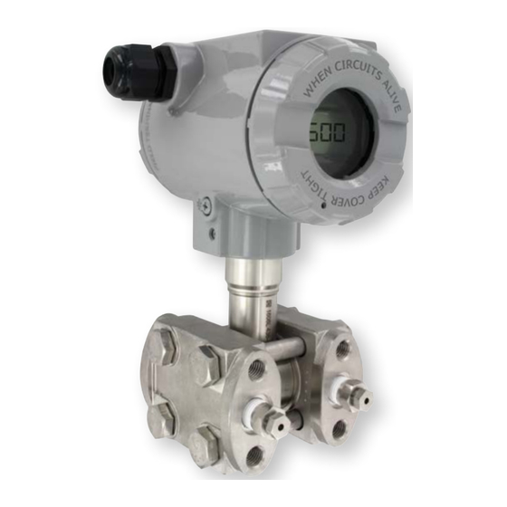
Series 3400 and 3500 Smart Pressure Transmitters
Specifications - Installation and Operating Instructions
5-1/4 [132]
The Series 3400 and 3500 Smart Pressure Transmitters are microprocessor-based
high performance transmitters, which have flexible pressure calibration, push button
configuration, and are programmable using HART
3400 and 3500 are capable of being configured with three push buttons located
inside the front cover of the units (a field calibrator is not required for configuration.)
The transmitter software compensates for thermal effects, improving performance.
EEPROM stores configuration settings and stores sensor correction coefficients in the
event of shutdowns or power loss. The 3400 and 3500 can be configured to be ATEX/
IECEx approved for use in hazardous (Classified) locations. The rangeability allows
the smart transmitter to be configured to fit most applications.
FEATURES/BENEFITS
• High accuracy (±0.075% FS)
• 3400 Rangeability (up to 100:1)
• 3500 Rangeablility (up to 25:1)
• Completely configurable using push buttons (no calibrator required)
• Fail-mode process function
• Automatic ambient temperature compensation
APPLICATIONS
• Water and wastewater
• Chemical and petrochemical
• Pulp and paper
• Oil and gas
• Food and beverage
• Filter or pump differential pressure
• Critical process monitoring
DWYER INSTRUMENTS, INC.
P.O. BOX 373 • MICHIGAN CITY, INDIANA 46360, U.S.A.
5-1/4 [133]
3-5/8
4
[91.5]
[102]
1-1/2 [38.5]
2 X M6
1/2˝ NPT [MALE]
PROCESS
CONNECTION
Communication. The Series
®
1
5-1/4 [132]
SPECIFICATIONS
3400 SPECIFICATIONS
Service: Compatible gases, steam,
liquids, or vapors.
Wetted Materials: 316L SS.
Accuracy: ±0.075% FS (@20°C).
Rangeability: Up to 100:1 turn down.
Stability: ≤0.075% FSO/3 years.
Temperature Limits: Ambient: -40 to
185°F (-40 to 85°C); Process w/ -DS: -40
to 400°F (-40 to 204.4°C).
Thermal Effect: <±0.05% span/10°C.
Power Requirements: 10-55 VDC.
Output Signal: 4-20 mA.
Response Time: 16 to 480 ms
(programmable).
Dampening Time: 0 to 60 s.
Electrical Connections: Packing gland
M20x1.5, two 1/2˝ female NPT conduit,
screw terminal.
Process Connection: 1/2˝ female or
male NPT.
Enclosure Rating: NEMA 4X IP66/IP67.
Agency Approvals: CE; -IS, -FP suffix:
ATEX Compliant
2813
II 2G Ex ia/
db IIC T6/T5 Gb Ta<80°C, T5 / II 2D Ex
ia/tb IIIC T85°C/T100°C Db. Type
Certificate No. KDB 17ATEX0056X.
ATEX Standards: EN 60079-
0:2012+A11:2013,
EN 60079-1:2014, EN 60079-11:2012,
EN 60079-26:2015, EN 60079-31:2014
IECEx Compliant: Ex ia/db IIC T6/
T5 Gb / Ex ia/tb IIIC T85°C/T100° Db.
Certificate of Conformity IECEx KDB
17.0008X. IECEx Standards: IEC 60079-
0:2011, IEC 60079-1:2014-06, IEC
60079-11:2011, IEC 60079-26:2006, IEC
60079-31:2013.
Phone: 219/879-8000
Fax: 219/872-9057
Bulletin P-3400-3500
5-1/4 [133]
3-5/8
4
[91.5]
[102]
2 X M6
1/4˝ NPT [FEMALE]
PROCESS
CONNECTIONS
3500 SPECIFICATIONS
Service: Compatible gases, steam,
liquids, or vapors.
Wetted Materials: 316L SS and FPM;
with Diaphragm Seal: 316L SS.
Accuracy: ±0.075% FS (@20°C).
Rangeability: Up to 25:1 turn down.
Stability: ≤0.075% FSO/3 years.
Temperature Limits: Ambient: -40 to
185°F (-40 to 85°C); Process w/ -DS: -40
to 400°F (-40 to 204.4°C).
Thermal Effect: <±0.05% span/10°C.
Power Requirements: 10-55 VDC.
Output Signal: 4-20 mA.
Response Time: 16 to 480 ms
(programmable).
Dampening Time: 0 to 60 s.
Electrical Connections: Packing gland
M20x1.5, two 1/2˝ female NPT
conduit, screw terminal.
Process Connection: 1/4˝ female NPT.
Enclosure Rating: NEMA 4X IP66/IP67.
Agency Approvals: CE; -IS, -FP suffix:
ATEX Compliant
2813
II 2G Ex
ia/db IIC T6/T5 Gb Ta<80°C, T5 / II 2D
Ex ia/tb IIIC T85°C/T100°C Db. Type
Certificate
No. KDB 17ATEX0056X. ATEX
Standards: EN 60079-0:2012+A11:2013,
EN 60079-1:2014, EN 60079-11:2012,
EN 60079-26:2015, EN 60079-31:2014
IECEx Compliant: Ex ia/db IIC T6/
T5 Gb / Ex ia/tb IIIC T85°C/T100° Db.
Certificate of Conformity IECEx KDB
17.0008X. IECEx Standards: IEC 60079-
0:2011, IEC 60079-1:2014-06, IEC
60079-11:2011, IEC 60079-26:2006, IEC
60079-31:2013.
www.dwyer-inst.com
e-mail: info@dwyermail.com
Advertisement
Table of Contents

Related Manuals for Dwyer Instruments 3400 Series


Summary of Contents for Dwyer Instruments 3400 Series
- Page 1 17.0008X. IECEx Standards: IEC 60079- 0:2011, IEC 60079-1:2014-06, IEC 0:2011, IEC 60079-1:2014-06, IEC 60079-11:2011, IEC 60079-26:2006, IEC 60079-11:2011, IEC 60079-26:2006, IEC 60079-31:2013. 60079-31:2013. DWYER INSTRUMENTS, INC. Phone: 219/879-8000 www.dwyer-inst.com P.O. BOX 373 • MICHIGAN CITY, INDIANA 46360, U.S.A. Fax: 219/872-9057 e-mail: info@dwyermail.com...
- Page 2 Explanation of Symbols: Symbol Description Warning to proceed strictly in accordance with the information contained in the documentation in order to ensure the safety and full functionality of the device. Information particularly useful during installation and operation of the device. Information particularly useful during installation and operation of an Ex device.
-
Page 3: Table Of Contents
4.2. 3400 and 3500 transmitters in Exi version or Exd version have additional TABLE OF CONTENTS markings as described in Appendix II or Appendix I. FEATURES, INSTALLATION AND MAINTENANCE OF TRANSMITTERS ..3 4.3. The transmitters in all versions comply the requirements of the RoHS INTRODUCTION . - Page 4 5.1.3. Enclosure ingress protection 5.2.3. Metrological parameters IP 66,67 according to EN 60529 Accuracy ≤ ± 0.075% for the 5.1.4. Response time on pressure stroke calibrated range In response to the pressure stroke measured by the transmitter - full Long term stability ≤...
- Page 5 5.3.3. Series 3500, Metrological parameters Accuracy ≤ ±0.075% (FSO) of the calibrated range ≤ ±0.1% (FSO) for range -80, -50 91.5 Long term stability ≤ accuracy / 3 years M20 X 1.5 CABLE GLAND or ≤ 2 x accuracy / 5 years 2 X M6 CABLE Ø6 - Ø12 Error due to supply voltage changes...
-
Page 6: Construction
6. CONSTRUCTION Connection of the 3400 and 3500 transmitter 6.1. Principle of measurement. Electronic system construction Connect as shown in Figure 10a. If it is necessary to enable communication The electrical signal from the sensor, which is proportional to the pressure, with the transmitter, a communicator or converter can also be connected. -
Page 7: Place Of Installation
7.2. Low Ambient Temperature 345Ø WITH 15Ø PITCH When the solidification point of the liquid whose pressure is being measured is higher than the ambient temperature, steps should be taken to protect the measurement apparatus from freezing effects such as medium expansion. - Page 8 8.2.2. The Series 3500 transmitters with connecting cover (Figure 1) are designed for installation on 3-valve or 5-valve manifolds to a 2˝ pipe or to a flat surface using the mounting bracket shown in Figure 8, and Figure 9. 173.5 IN HS VERSION 175.5 IN EXD VERSION Ø35 - Ø65 187.5 IN HS AND EXD VERSION...
-
Page 9: Electrical Connection
9. ELECTRICAL CONNECTION Communicator or converter connection to the transmitter’s terminals 9.1. General recommendations In order to enable local communication by connecting a communicator or 9.1.1. It is recommended that twisted pair cabling be used for the signal lines. converter to the transmitter’s terminals, make sure that the resistance Ro If the transmitter and signal line are subject to a large amount of from the transmitter’s terminals to the power supply source lies within the electromagnetic interference, then shielded cable should be used. -
Page 10: Setting And Regulation
If Ro in current loop is lower than 240Ω is necessary to connect 240Ω 10.2.3. It is possible to carry out a “pressure zeroing” procedure, for example to resistor to current loop by remove jumper from <SIGNAL-> and <TEST-> compensate for measurement deviation caused by a change in position terminals. - Page 11 BACK BACK PV ZERO IN H2O IN HG DONE FT H2O MM H2O MM HG BACK BYPRES BYVALU MBAR G/SQCM BACK KG/SQCM BYPRES BYVALU +/- ______ BACK TORR 0[S] DONE 2[S] MENU M H2O 5[S] ______ INH2O4 EXIT 10[S] MMH2O4 PV ZERO 30[S] DONE...
-
Page 12: Of The Inspections And Spare Parts
The selected unit should be confirmed by pressing [◙] for 1 second. 10.2.5.2. Local Menu, error reports. After confirmation the transmitter will display “DONE” or report During command entry, an error code may be displayed indicating the error number. The “← BACK” option allows navigation up one an invalid command. - Page 13 Display backlighting - Local display is equipped with a backlight. remotely using computer and Raport 2 software according to 10.2.4 or Figure 4 shows how to change the display position by rotation. locally with transmitter buttons (up to 1% only) according to 10.2.5 of the Manual.
-
Page 14: Packing, Storage And Transport
Example: If a communicator is connected to the power supply line of the transmitter, a fault in the line may be indicated by the message “No response” or “Check connection”. If the line is in order, check the operation of the transmitter. 11.3. - Page 15 • Device is not field-repairable and should be returned to the transmitter together with process connections may be installed within a Dwyer Instruments, Inc. if repair is needed. Type 1 (21) or Type 2 (22) hazardous zone In areas where there is a risk of dust explosion, transmitters in...
- Page 16 4.4 Transmitters may be used in ambient temperatures (Ta) between -40ºC < Ta W.E. Anderson ≤45ºC for class T6 or between -40ºC < Ta ≤ 45°C for class T6 or between Attn. Repair Department -40°C < Ta 75ºC for T5. 250 High Grove Rd Grandview, MO 64030 4.5 Transmitter sensor diaphragm should not be subject to damage during...
- Page 17 • Device is not field-repairable and should be returned to GENERAL CAUTION Dwyer Instruments, Inc. if repair is needed. • Protection provided by the equipment may be impaired if the equipment In areas where there is a risk of dust explosion, transmitters in WARNING is used in a manner not specified by the manufacturer.
- Page 18 7. Electrical connections If Uo < UQ The parameters UQ, Io, and Po are interrelated as follows: UQ = 4Po Rw = UQ Po = Uo (UQ –Uo) for Uo ≤ 1/2UQ HAZARDOUS AREA SAFE AREA 6.5. For power supplies with a rectangular characteristic: Ui = 24 V Ii = 0.025 A Pi = 0.6 W...
- Page 19 APPENDIX III Diaphragm Seals Configuration of the Series 3500 transmitters to measure the level, density of liquid and phase boundary Recommendations The version of the transmitter with two remote diaphragm seals is recommended To simplify the mathematical operations we introduce the density coefficent of the for the measurement of pressure differences when the hydrostatic pressure of the medium Xρ...
- Page 20 Please recycle where facilities exist. Check with your Local Authority or retailer for recycling advice. HART is a registered trademark of Hart Communication Foundation ® ©Copyright 2020 Dwyer Instruments, Inc. Printed in U.S.A. 7/20 FR# 444400-10 Rev. 1 DWYER INSTRUMENTS, INC. Phone: 219/879-8000 www.dwyer-inst.com...
Need help?
Do you have a question about the 3400 Series and is the answer not in the manual?
Questions and answers