Table of Contents
Troubleshooting

Related Manuals for Solar Stik 24VDC PRO-VERTER 7000-120 AGS


Summary of Contents for Solar Stik 24VDC PRO-VERTER 7000-120 AGS
- Page 1 OPERATOR AND MAINTENANCE MANUAL FOR THE 24VDC PRO-VERTER 7000-120 AGS PN: 20-0104016 DISTRIBUTION STATEMENT A. Approved for public release; distribution is unlimited. Rev – Version 1.0 Updated:20200817 August 2020 Solar Stik , Inc. ®...
-
Page 2: Table Of Contents
24VDC PRO-Verter 7000-120 AGS Operator Manual Contents GENERAL INFORMATION, THEORY OF OPERATION, AND EQUIPMENT DESCRIPTION PRO-Verter Introduction . . . . . . . . . . . . . . . . . . . . . . . . . . . . . . . . . . . . . . . . . . . . . . . 6 Capabilities and Controls Important Product Safety Information and Instructions . - Page 3 24VDC PRO-Verter 7000-120 AGS Operator Manual Foreign Object Debris (FOD) and Water Intrusion ....... . 25 Meter Circuits .
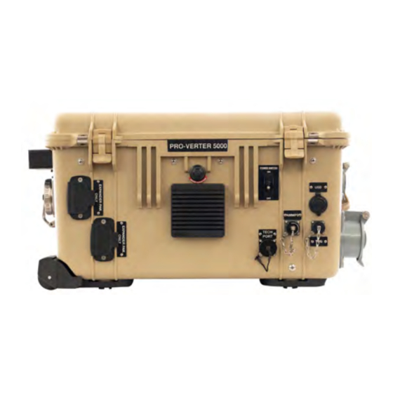
- Page 4 Contact . . . . . . . . . . . . . . . . . . . . . . . . . . . . . . . . . . . . . . . . . . . . . . . . . . . . . . . 79 List of Figures Figure 1. A PRO-Verter in an HPS ............................ 6 Figure 2. 24VDC PRO-Verter 7000-120 AGS ........................8 Figure 3. PRO-Verter primary circuits ..........................16 Figure 4. Invert and charge mode LEDs on User Interface .................... 20 Figure 5.
- Page 5 24VDC PRO-Verter 7000-120 AGS Operator Manual Revision History Section Page(s) Description Date First published Feb 2019 August 2020 Solar Stik , Inc. ®...
-
Page 6: General Information, Theory Of Operation, And Equipment Description
24VDC PRO-Verter 7000-120 AGS Operator Manual GENERAL INFORMATION, THEORY OF OPERATION, AND EQUIPMENT DESCRIPTION PRO-Verter Introduction The primary function of a Portable Remote Operation – Inverter/Charger (PRO-Verter) is to serve as the central power management device in a circuit where both Alternating Current (AC) and Direct Current (DC) are present and being used. -
Page 7: Capabilities And Controls
24VDC PRO-Verter 7000-120 AGS Operator Manual Capabilities and Controls The PRO-Verter provides specific capabilities for a System in which it is employed, but Systems vary in accordance with the application requirements, and not every feature in the PRO-Verter may be used for an application. The PRO-Verter is delivered pre-programmed at the factory for the customer’s application, and only minor programming adjustments are occasionally needed in the... -
Page 8: Important Product Safety Information And Instructions
24VDC PRO-Verter 7000-120 AGS Operator Manual Important Product Safety Information and Instructions This manual contains important safety instructions that must be followed during the installation and operation of the 24VDC PRO-Verter 7000-220 AGS. Read all instructions and safety information contained in this manual. -
Page 9: Safety Information Labels
Since the use of this manual and the conditions or methods of operation, use, and maintenance of this product are beyond the control of Solar Stik, this company does not assume responsibility and expressly disclaims liability for loss, damage, or expense—whether direct, indirect, consequential, or incidental—arising out of or anyway connected with such operation, use, or maintenance. -
Page 10: Fire Hazard
24VDC PRO-Verter 7000-120 AGS Operator Manual Fire Hazard Fire Types Class A fire - Fires in ordinary combustibles such as wood, paper, cloth, trash, and plastics. Class B fire - Fires in flammable liquids such as gasoline, petroleum, oil, and paint. -
Page 11: Electric Shock Hazard
• Disconnect power before performing maintenance. • Wear safety glasses whenever working on any part of a System that requires exposure to mechanical or direct electrical contacts. WARNING The 24VDC PRO-Verter 7000-120 AGS is NOT GFCI protected. August 2020 Solar Stik , Inc. ®... -
Page 12: Environmental And Handling Precautions
24VDC PRO-Verter 7000-120 AGS Operator Manual Environmental and Handling Precautions All components are ruggedized, yet there are a few things the operator can do to prevent failures and prolong the operational life of the product. Water If outdoor operation is necessary, the lids of all components should be closed and latched. -
Page 13: Theory Of Operation
24VDC PRO-Verter 7000-120 AGS Operator Manual Theory of Operation Models of Operation Depending on the application, there are several operational models that can be configured using a PRO-Verter: DC-only/Inverter (automatic functions) Operating conditions – All power generated is from DC generators and AC loads are supported by the PRO-Verter’s Inverter function using energy stored in batteries. -
Page 14: Selecting A Generator/Grid Ac Source
24VDC PRO-Verter 7000-120 AGS Operator Manual UPS (automatic functions) Operating conditions – A PRO-Verter connects critical AC loads directly to grid/utility or prime AC power when it is available, and provides backup power for the load by supplying Inverter AC (using energy from a connected battery bank) when the Grid-Utility or Prime AC source is interrupted. -
Page 15: The Load Support Model
AC power source. Surges and/or overloads can occur at the AC source when the transfer switch engages, causing it to shut down or overload. Consult Solar Stik Technical Support when configuring the PRO-Verter programming for a particular AC source. -
Page 16: Pro-Verter Circuits And Functions
24VDC PRO-Verter 7000-120 AGS Operator Manual PRO-Verter Circuits and Functions A PRO-Verter is the central power management device (i.e. the “brain”) for a Hybrid or High- Efficiency Electrical System. At its core, the PRO-Verter has a combination inverter/charger, which operates in concert with its supporting circuits to provide the operator with a multifaceted solution... -
Page 17: Load Prioritization
24VDC PRO-Verter 7000-120 AGS Operator Manual Load Prioritization The PRO-Verter has a “one-track mind” when it comes to managing power – In every operation mode it is entirely focused on maintaining constant power to the load. This function is key to understanding how the PRO-Verter behaves. -
Page 18: Pass-Through" Power And The Internal Ac Transfer Switch
24VDC PRO-Verter 7000-120 AGS Operator Manual INPUT (FAVS 03) setting should be set to the same value of the maximum AC power output rating of the source. For example, if the generator is rated for 3000 Watts continuous output, then the AC INPUT should be set for 25 Amps for @ 120 VAC or 13.6 A @ 220 VAC (=3000 Watts). -
Page 19: Charge Function
24VDC PRO-Verter 7000-120 AGS Operator Manual Qualifying AC Input Power The PRO-Verter must only be used with AC sources that generate or provide pure sinusoidal waveforms with voltage and frequency that meet minimum standards. When an active AC source is connected to the PRO-Verter, it will “qualify” the power before passing it through to the load and initiating the battery charging sequence. -
Page 20: Invert Function
24VDC PRO-Verter 7000-120 AGS Operator Manual LEDs on the User Interface indicate when the PRO-Verter is inverting or charging Figure 4. Invert and charge mode LEDs on User Interface Invert Function The PRO-Verter’s Invert function transforms DC from a connected battery into pure sine-wave AC power for an AC load. -
Page 21: Testing The Ags Function
24VDC PRO-Verter 7000-120 AGS Operator Manual When the AGS is active during hybrid operation, it might only start/stop a generator as a last line of defense to ensure continuity of power is available to the load when the batteries are at low SOC. -
Page 22: Cooling Fan Operation
24VDC PRO-Verter 7000-120 AGS Operator Manual Cooling Fan Operation The PRO-Verter contains two (2) variable-speed internal cooling fans that are controlled automatically. The speed of these fans is determined either by the PRO-Verter internal temperature or by the load on the transformer. -
Page 23: Recommended Operation Environment (Location)
24VDC PRO-Verter 7000-120 AGS Operator Manual Recommended Operation Environment (Location) The PRO-Verter is designed for operation in extreme temperatures and dusty or wet environmental conditions, but proper placement and care are necessary to mitigate against their effects. Preferred operation locations are shaded, well ventilated, dry, and clean. If operated outdoors with direct exposure to the elements, it is highly recommended that the case lid be closed and latched to prevent water/particulate intrusion and prevent sun damage to the LCD at the User Interface. -
Page 24: Pro-Verter Internal Cooling
24VDC PRO-Verter 7000-120 AGS Operator Manual the protection circuits will engage and shut down the transformer to prevent damage. • “FET OVERTEMP” - When the temperature reported from the FET sensor reaches 185ºF (85ºC), the FET circuit will shut down to protect itself from damage. -
Page 25: Foreign Object Debris (Fod) And Water Intrusion
24VDC PRO-Verter 7000-120 AGS Operator Manual Foreign Object Debris (FOD) and Water Intrusion ALL Solar Stik equipment is designed for operation in adverse environmental conditions, however, certain rules apply: 1. If operating in wet environments, use common-sense placement to avoid water intrusion by either flooding or precipitation. -
Page 26: Equipment Description
24VDC PRO-Verter 7000-120 AGS Operator Manual Equipment Description The Inter-Connect System The System is comprised of three (3) distinct types of technologies: • Energy storage • Power management • Power generation All of the individual components that operate in these categories utilize a unique connection architecture known as the Inter-Connect Circuit. -
Page 27: Circuit Breaker Protections
24VDC PRO-Verter 7000-120 AGS Operator Manual Circuit Breaker Protections The Inter-Connect network is protected from overloads and short circuits through a network of circuit breakers strategically placed throughout the circuit. It ensures that the potential for a reverse polarity connection within the circuit is minimized. If a problem occurs in a leg of the Inter- Connect Circuit, the affected leg will disconnect from the primary network, leaving the other circuits functioning. -
Page 28: Pro-Verter 7000
24VDC PRO-Verter 7000-120 AGS Operator Manual PRO-Verter 7000 Connections and Cooling Note: Ports and placards vary among PRO-Verters according to model selected. Description Connector Voltage Amps Watts Battery Input Connection Inter-Connect Port 24 VDC 100 A 2400 W Power Switch... -
Page 29: The Information Plate
24VDC PRO-Verter 7000-120 AGS Operator Manual Description Connector Voltage Amps Watts 120VAC Output L14-30R 120 VAC 30 A 3600 W HBL2710SW Air Intake Vent 120VAC Output L5-20R 120 VAC 20 A 2400 W HBL61CM65 24VDC Accessory Port Inter-Connect 24 VDC... -
Page 30: Faceplate Features And Descriptions
PRO-Verter and to control and monitor the status of the System. The PRO-Verter is programmed at Solar Stik to meet the specifications of a specific application. Programming mode is blocked and password protected but can be accessed if reprogramming is required by contacting Solar Stik Technical Support (800-793-4364 Ext. -
Page 31: Pro-Verter Lcd User Interface
24VDC PRO-Verter 7000-120 AGS Operator Manual AC IN and AC OUT Breakers – Circuit breakers protect against overcurrent conditions in dedicated circuits. If too much amperage flows due to short-circuit, inadequate or improper loading, or component failure, these will protect the system and operator. -
Page 32: Table 1. Led System Status Indicator Guide
24VDC PRO-Verter 7000-120 AGS Operator Manual Table 1. LED System Status Indicator Guide Status Meaning (1) PRO-Verter is disabled; (2) User interface is in Power Save mode —press any button to activate LEDs; (3) No power to user interface (check cable or the power to the inverter); or (4) No AC power at the inverter’s AC output terminals. -
Page 33: Understanding The User Interface Menus
24VDC PRO-Verter 7000-120 AGS Operator Manual Understanding the User Interface Menus The PRO-Verter menu options and programming features in the User Interface were developed over 10 years using real data and feedback from users around the world. They allow PRO-Verter functions to be configured in exact accordance with mission requirements, and support operation in a flexible “open”... -
Page 34: Rotary Select Knob
24VDC PRO-Verter 7000-120 AGS Operator Manual SETUP The SETUP menu contains the prime programming for PRO-Verter operation. Nearly every function the PRO-Verter manages can be accessed and controlled from within the SETUP menus. The menus are configured at the factory in accordance with application information provided by the customer, and the programming is usually protected from unauthorized access by a passcode. -
Page 35: Overview To The User Interface Menu Windows
24VDC PRO-Verter 7000-120 AGS Operator Manual Overview to the User Interface Menu Windows The columns below provide a condensed version of the menu windows that constitute the menu tree of each button. Figure 15. Menu buttons on the LCD user interface... -
Page 36: Programming Menu Map
Light green menu items represent resettable menu selections. Press and hold the knob for 3 seconds to reset values. Orange menu items indicate values set by Solar Stik for a specific application. These values (with the exception of setting the clock to local time) should not be changed by the user without consulting tech@solarstik.com. -
Page 37: Meter Button Menus: Read-Only Displays
24VDC PRO-Verter 7000-120 AGS Operator Manual METER Button Menus: Read-only Displays METER Status 01 DC Meters 01A DC Volts 01B DC Amps 26.2 VDC 0 Amps Status 02 AC Meters 02A Output Volts 02B Load Amps 02C Input Amps 02D Inv/Chg Amps... -
Page 38: Setup Button Menus
24VDC PRO-Verter 7000-120 AGS Operator Manual SETUP Button Menus SETUP: 01 System Setup and 02 Inverter Setup SETUP 01 System Setup 01A Set Clock Range: 12:00AM - 12:00PM (NOTE: Ensure that the clock is set to local time.) 11:18AM Set Clock... - Page 39 24VDC PRO-Verter 7000-120 AGS Operator Manual SETUP Button Menus continued Setup: 03 Charger Info: With CC/CV selected, the following SETUP menus are no longer accessible and will Status 03 Charger Setup display “CC/CV Controlled” when they are selected: 01D Max Charge Amps, 03D...
- Page 40 24VDC PRO-Verter 7000-120 AGS Operator Manual SETUP Button Menus continued Setup: 04 AGS Setup continued SETUP Status AGS Function Notes 04 AGS Setup • After 15 seconds at or below 25.0 V, the PRO-Verter sends the 04A Gen Run VDC Press Select start signal to the Generator.
- Page 41 24VDC PRO-Verter 7000-120 AGS Operator Manual SETUP Button Menus continued SETUP: 04 AGS Setup continued SETUP Status 04 AGS Setup 04E Gen Run Temp Ext Input Set Gen Run Temp Set Gen Run Temp Set Gen Run Temp Start = OFF...
- Page 42 24VDC PRO-Verter 7000-120 AGS Operator Manual SETUP Button Menus continued Setup: 04 AGS Setup, 05 BMK Setup continued SETUP Default Off 04K Gen 100% SOC Range: Off, 1-255 Start Days = Off Set Gen 100% SOC Set Gen 100% SOC...
-
Page 43: Tech Button Menus
24VDC PRO-Verter 7000-120 AGS Operator Manual TECH Button Menus Inv BTS ###F TECH Inv Tfmer ###F Inv FETs ###F Read-only Displays 01 Temperatures AGS Sensor ###F Press Select ACLD Temp ###F PT BTS ###F PT FETs ###F 01 Temperatures PT Inductor... -
Page 44: Operator Instructions
24VDC PRO-Verter 7000-120 AGS Operator Manual OPERATOR INSTRUCTIONS Power Up the PRO-Verter The PRO-Verter must be connected to a 24 VDC power source (such as 24VDC Expander Paks) to operate. When the PRO-Verter is connected to an active DC circuit and is powered on, the master control board that commands the various internal circuits performs an internal diagnostic check to ensure the functions can be safely used. -
Page 45: Adjust The Ac Input Setting
24VDC PRO-Verter 7000-120 AGS Operator Manual Adjust the AC INPUT Setting The AC INPUT setting can control several aspects of the PRO-Verter’s AC-related functions: • AC Power Management • Generator/Grid • Charge Amperage Rates • Load Support Engagement (if installed) Setting the AC Input for “Nominal-load”... -
Page 46: Overload" Conditions
24VDC PRO-Verter 7000-120 AGS Operator Manual “Overload” Conditions Over-loading of the PRO-Verter can occur under the following conditions: • Load AC power demand is greater than the inverter’s rated power output • Load AC power demand is greater than the rated output of the connected AC power source (generator or grid-utility) •... -
Page 47: Troubleshooting Procedures
24VDC PRO-Verter 7000-120 AGS Operator Manual generator, the AC INPUT setting must be set to limit the AC power the PRO-Verter will expect from the AC source. In this scenario, it is possible for the PRO-Verter to put up to 130% load on the AC source (generator or grid-utility), which can occur when charging mode is engaged and a sudden AC surge is demanded by the load. -
Page 48: Generator Status Leds
24VDC PRO-Verter 7000-120 AGS Operator Manual Generator Status LEDs The PRO-Verter Auto Generator Start activity is reported by LEDs on the Faceplate (Figure 18). The “READY” LED is on the left and the STATUS is on the right. Figure 18. Generator Status LEDs and AGS Test Button •... -
Page 49: Pro-Verter Lcd Screen Troubleshooting Table
24VDC PRO-Verter 7000-120 AGS Operator Manual PRO-Verter LCD Screen Troubleshooting Table If the display is not functioning correctly, use Table 2 to help find a solution. Table 2. Troubleshooting the LCD Screen Symptom Possible Cause(s) Solution Remove the LCD user interface and... -
Page 50: Maintenance Instructions
24VDC PRO-Verter 7000-120 AGS Operator Manual MAINTENANCE INSTRUCTIONS Preventive Care and Maintenance Note: The function and efficiency of all electronic equipment is related to and dependent upon the temperature at which it is operating. It performs optimally within a narrow temperature range and less so as the temperature falls outside of that range. -
Page 51: Water Intrusion-Prevention And Remediation
24VDC PRO-Verter 7000-120 AGS Operator Manual Water Intrusion—Prevention and Remediation WARNING Standing water around the electrical equipment or intrusion of water into the System components can increase the risk of electrical shock. The lid on the PRO-Verter should be closed whenever possible while the System is operating to •... -
Page 52: Pro-Verter/Inverter Reset
24VDC PRO-Verter 7000-120 AGS Operator Manual PRO-Verter/Inverter Reset To perform an inverter reset: 1. Ensure all AC power (i.e., shore power or generator) is removed from the PRO-Verter. 2. Remove the PRO-Verter Faceplate. The control board on which the RESET button and RESET LED are mounted is in the center of the PRO-Verter (see below). -
Page 53: Quick Links To Statuses, Faults, And Resolutions Reported By The Pro-Verter
24VDC PRO-Verter 7000-120 AGS Operator Manual Quick Links to Statuses, Faults, and Resolutions Reported by the PRO-Verter This guide is interactive if used on a computer or handheld device. Each of the faults in the lists below is touch-linked to an explanation of the fault and a solution to resolve the fault. -
Page 54: Pro-Verter Inverter Mode Status Messages
Unknown Mode ## This status message displays when the inverter/charger has sent an operational status code that is unrecognized. Solution Call Technical Support at Solar Stik for assistance in identifying and understanding the actual fault status. Back to Quick Links page... -
Page 55: Pro-Verter Charge Mode Status Messages
24VDC PRO-Verter 7000-120 AGS Operator Manual PRO-Verter Charge Mode Status Messages When AC power (grid utility or generator) is connected to the PRO-Verter, it automatically begins to monitor the AC input for acceptable voltage. After the AC input is accepted, the AC transfer relay (inside the PRO-Verter) closes and Charge mode begins. - Page 56 24VDC PRO-Verter 7000-120 AGS Operator Manual Charger Standby This indicates the charger has been disabled to prevent further charging, but the AC power (from utility or generator) to the AC input is still available on the AC output. This display is shown when the CHARGER ON/OFF button is pressed while the AC power is passing through the inverter/ charger.
-
Page 57: Pro-Verter Charger Problems: Solutions And Explanations
24VDC PRO-Verter 7000-120 AGS Operator Manual PRO-Verter Charger Problems: Solutions and Explanations Unit won’t transfer to Charge mode when connected to generator or grid AC Solution: Is the charge (CHG) LED on the user interface blinking? If not, the charger does not recognize the incoming AC as being within acceptable limits. -
Page 58: Pro-Verter Inverter Problems: Solutions And Explanations
24VDC PRO-Verter 7000-120 AGS Operator Manual PRO-Verter Inverter Problems: Solutions and Explanations Most faults (inverter, AGS, and BMK) also alternate with the inverter/charger status. The FAULT LED comes on and a fault status is displayed by the LCD user interface when an abnormal condition is detected. - Page 59 To resume normal operation, reduce the load to within normal operating parameters. Shade the PRO-Verter to reduce solar loading. Clean the air filters if they are dirty. If this fault does not clear after doing the power reset, the inverter will require service contact Solar Stik Technical Support. High Battery The inverter has turned off because the battery voltage is at a very high level.
- Page 60 24VDC PRO-Verter 7000-120 AGS Operator Manual Solution: This fault may occurs when an external DC charging source is charging the inverter’s battery bank. Turn off any other additional charging source to allow the DC voltage level to drop. Check the Power Hub to ensure that it is functioning properly. Refer to the Power Hub Operator Manual.
- Page 61 24VDC PRO-Verter 7000-120 AGS Operator Manual Overcurrent This fault may be the result of an excessive AC load and causes the inverter to shut down to protect internal power components. If the overload condition lasts for less than 10 seconds, the unit automatically restarts and resumes operation.
- Page 62 After resetting the inverter, press the INVERTER ON/OFF button on the user interface to turn the inverter on and then verify that the fault has cleared (i.e., manual restart). If the internal fault remains or returns, the inverter may require repair at a Solar Stik. Call Solar Stik Technical Support: 800-793-4364, Ext 102.
-
Page 63: Pro-Verter Ags Functional Tests
24VDC PRO-Verter 7000-120 AGS Operator Manual PRO-Verter AGS Functional Tests These tests are applicable when the PRO-Verter is connected to a fuel driven generator that has been modified with a Remote-start Enabling Kit (RsEK). When the autostart/autostop settings have been established and programmed, perform the following tests to verify that the AGS system is functioning correctly and there is communication between the user interface / inverter and the AGS. - Page 64 24VDC PRO-Verter 7000-120 AGS Operator Manual AGS Start Statuses Table (Meter 04) The following “Start” statuses identify the condition that autostarted the generator. The list below includes all possible statuses. If the autostart condition occurred sooner than expected, or it was not the intended autostart condition, refer to step 2 of System Initialization and Calibration in the Solar Stik System Setup and Operation Manual to change (or disable) the autostart setting.
- Page 65 24VDC PRO-Verter 7000-120 AGS Operator Manual AGS Operational Statuses (Meter 04) AC In The inverter/charger is connected to another source, such as a grid or an alternate generator, and is not controlled by the AGS. When AC In displays, the AGS is prevented or locked out from all autostarting conditions, except for when the generator needs to exercise—if enabled.
- Page 66 DC voltage. The faults highlighted in this section in orange are the only ones that could appear in a PRO-Verter programmed to work in a Solar Stik HPS . Fault Gen Run Symptoms: Generator is overloading and shutting down; the generator successfully started and ran for more than two (2) minutes, but the generator unexpectedly stopped before the active AGS autostop condition was finished.
- Page 67 24VDC PRO-Verter 7000-120 AGS Operator Manual For these AGS faults, refer to the Solution immediately following . Fault Test The generator failed to autostart and run after the red TEST button on the Faceplate is pressed on the AGS controller.
- Page 68 24VDC PRO-Verter 7000-120 AGS Operator Manual Fault MaxRn Generator turned off because the SETUP: 04F Max Gen Run Time setting had been met. This fault can occur when the autostop condition (FAVS F5: Gen Run VDC) exceeded the Max Gen Run Time setting.
-
Page 69: Pro-Verter Battery Monitoring Kit (Bmk) Statuses
The BMK is not communicating with the inverter/user interface. BMK Not Present View the BMK sense module’s LED (Contact Solar Stik Technical Support for assistance). a. If the LED is green, disconnect the terminal block for 5 seconds, and then reconnect it to ensure the terminal block is correctly seated into the sense module. - Page 70 Solution: Reset the battery monitor by removing all power from the BMK. If the fault remains or returns after resetting, the BMK may require repair. Contact Solar Stik Technical Service. Unknown Fault ## This fault message displays when the BMK has sent a fault code that is not recognized by the user interface.
-
Page 71: Fault History (Tech 04)
24VDC PRO-Verter 7000-120 AGS Operator Manual Fault History (Tech 04) Tech 04 in the LCD user interface provide provides the fault history for the inverter (04A) and the AGS (04B). The following is an example of how to read and understand the fault history in 04B AGS Faults The following is an example describing how to access AGS Faults . -
Page 72: Pro-Verter: Historical Data Collection
24VDC PRO-Verter 7000-120 AGS Operator Manual PRO-Verter: Historical Data Collection The PRO-Verters can provide some historical data for generator and battery operation. Press the METER button on the PRO-Verter Controller to access both the BMK and AGS functions. Scroll through 01 DC Meters, 02 AC Meters, 03 Timers until 04 AGS Meters or 05 BMK Meters is displayed. - Page 73 24VDC PRO-Verter 7000-120 AGS Operator Manual Auto Generator Start/Stop (AGS) Data Gen Run Time This menu displays the time the generator has been running since the AGS circuit autostarted the generator. This menu does not display run time when the generator has been manually started.
- Page 74 24VDC PRO-Verter 7000-120 AGS Operator Manual Battery Monitor (BMK) Data (Meter 05) This section describes what battery bank information is available from the battery monitor when using the LCD user interface. BMK Status This menu selection offers read only displays that give the current operating status of the battery monitor.
- Page 75 24VDC PRO-Verter 7000-120 AGS Operator Manual Total AH Out This meter displays the total amp hours removed from the battery since the PRO-Verter was first connected. This display can be used as a battery service life indicator. The value is displayed in 0.1 k [or 100 amp hours (“k”...
-
Page 76: Pro-Verter / Inverter Reset
Some older inverter models do not allow an inverter reset. If the inverter reset fails, you will need to perform a power reset using the procedure below. In either case, if an internal fault does not clear, call Solar Stik Technical Support at 800-793-4364 Ext 102. Power... -
Page 77: Supporting Information
24VDC PRO-Verter 7000-120 AGS Operator Manual SUPPORTING INFORMATION Technical Specifications General Environmental 24 VDC -4 °F to 140 °F Nominal Operating Voltage Operating Temperature (-20 °C to +60 °C) Input Battery Voltage Range 18 to 34 VDC Storage -40 °F to 158 °F... -
Page 78: Optional Remote Monitoring Kit (Rmk)
24VDC PRO-Verter 7000-120 AGS Operator Manual Optional Remote Monitoring Kit (RMK) The RMK provides remote access to vital operating data of the PRO-Verter via the user interface on the Faceplate. The RMK also records and stores all of the data from the PRO-Verter and provides tabular and graphical reports of these data in a user-friendly, browser-based user interface. -
Page 79: About Solar Stik, Inc
• Solar Stik New Equipment Training (on site) teaches Hybrid System configuration options with hands-on deployment of actual systems to enhance student understanding. Solar Stik Training Courses are tailored to the specific needs of the students. To schedule Solar Stik Training or to learn more about the curriculum, please contact us.
Need help?
Do you have a question about the 24VDC PRO-VERTER 7000-120 AGS and is the answer not in the manual?
Questions and answers