Sign In
Upload
Manuals
Brands
Solar Stik Manuals
Inverter
20-0104016
Solar Stik 20-0104016 Manuals
Manuals and User Guides for Solar Stik 20-0104016. We have
1
Solar Stik 20-0104016 manual available for free PDF download: Operator And Maintenance Manual
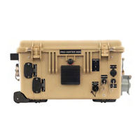
Solar Stik 20-0104016 Operator And Maintenance Manual (79 pages)
Brand:
Solar Stik
| Category:
Inverter
| Size: 1 MB
Table of Contents
Table of Contents
2
General Information, Theory of Operation, and Equipment Description
6
PRO-Verter Introduction
6
Figure 1. a PRO-Verter in an HPS
6
Capabilities and Controls
7
Important Product Safety Information and Instructions
8
Figure 2. 24VDC PRO-Verter 7000-120 AGS
8
Safety Information Labels
9
Limitations on Liability
9
Fire Hazard
10
Recommended Fire Extinguisher
10
Electric Shock Hazard
11
Environmental and Handling Precautions
12
Water
12
Impact
12
Dust/Foreign Object Intrusion
12
Heat
12
Theory of Operation
13
Models of Operation
13
DC-Only/Inverter (Automatic Functions)
13
Operating Conditions - All Power Generated Is from DC Generators and AC Loads Are Supported by the PRO-Verter's Inverter Function Using Energy Stored in Batteries
13
Hybrid (Automatic Functions)
13
Load Support (Automatic Functions)
13
Peak Power Delivery (Manual Functions)
13
Selecting a Generator/Grid AC Source
14
The Hybrid Model
14
UPS (Automatic Functions)
14
The Load Support Model
15
The Peak Power Delivery Model
15
Energy Storage Requirements for Operation
15
DC Voltage
15
PRO-Verter Circuits and Functions
16
Figure 3. PRO-Verter Primary Circuits
16
Load Prioritization
17
Real-Time Load Management
17
Pass-Through" Power and the Internal AC Transfer Switch
18
Charge Function
19
Invert Function
20
Automatic Generator Start/Stop (AGS) Function
20
Figure 4. Invert and Charge Mode Leds on User Interface
20
Testing the AGS Function
21
AGS Audible Alarm
21
Figure 5. AGS Status Leds
21
Cooling Fan Operation
22
Protection Circuits
22
EMI Circuit Protection
22
Circuit Limitations
22
Recommended Operation Environment (Location)
23
PRO-Verter Operation Temperature
23
Overheating and Derating
23
PRO-Verter Internal Cooling
24
Figure 6. PRO-Verter Temperature Vs. Performance Graphic
24
Foreign Object Debris (FOD) and Water Intrusion
25
Meter Circuits
25
Historical Data and Fault Tracking
25
Equipment Description
26
The Inter-Connect System
26
Circuit Breaker Protections
27
The Inter-Connect Plug
27
Figure 7. Inter-Connect Plug
27
PRO-Verter 7000
28
Connections and Cooling
28
Figure 8. PRO-Verter 7000-120 AGS Front Exterior
28
Figure 9. PRO-Verter 7000-120 AGS Left Exterior
28
The Information Plate
29
Figure 10. PRO-Verter 7000-120 AGS Right Exterior
29
Figure 11. PRO-Verter I-Plate
29
Faceplate Features and Descriptions
30
Figure 12. PRO-Verter Faceplate
30
PRO-Verter LCD User Interface
31
Figure 13. LCD User Interface
31
Table 1. LED System Status Indicator Guide
32
Understanding the User Interface Menus
33
Menus Overview
33
Rotary SELECT Knob
34
Example: How to Navigate the User Interface Menus
34
Figure 14. How to Start/Stop a Generator Manually
34
Overview to the User Interface Menu Windows
35
Figure 15. Menu Buttons on the LCD User Interface
35
Programming Menu Map
36
Menu Map Color Coding Key
36
FAVS Button Menus
36
CTRL Button Menus
36
METER Button Menus: Read-Only Displays
37
SETUP Button Menus
38
TECH Button Menus
43
Operator Instructions
44
Power up the PRO-Verter
44
Set the Clock
44
Figure 16. Powering up the PRO-Verter
44
Figure 17. Setting the PRO-Verter Clock
44
Adjust the AC INPUT Setting
45
Setting the AC Input for "Nominal-Load" Conditions
45
Proper Loading and Power Distribution
45
Overload" Conditions
46
Load Support Function
46
Lag Times and Surge Rates
46
Troubleshooting Procedures
47
Generator Status Leds
48
Figure 18. Generator Status Leds and AGS Test Button
48
PRO-Verter LCD Screen Troubleshooting Table
49
Table 2. Troubleshooting the LCD Screen
49
Maintenance Instructions
50
Preventive Care and Maintenance
50
Cleaning the Air Filters
50
Figure 19. Louvered Vent Cover
50
Figure 20. Air Filter
50
Figure 21. Cover and Filter Removed
50
Figure 22. PRO-Verter Air Intake Vent
50
Water Intrusion-Prevention and Remediation
51
Figure 23. Location of Drain Plug Screws in the PRO-Verter 7000
51
PRO-Verter/Inverter Reset
52
Quick Links to Statuses, Faults, and Resolutions Reported by the PRO-Verter
53
Quick Links to PRO-Verter Status Messages
53
Quick Links to Problems: Solutions and Explanations
53
PRO-Verter Inverter Mode Status Messages
54
PRO-Verter Charge Mode Status Messages
55
Figure 24. CC/CV, HOLD CV / CHG VDC Charging Profile
55
PRO-Verter Charger Problems: Solutions and Explanations
57
PRO-Verter Inverter Problems: Solutions and Explanations
58
PRO-Verter AGS Functional Tests
63
PRO-Verter Battery Monitoring Kit (BMK) Statuses
69
Fault History (Tech 04)
71
PRO-Verter: Historical Data Collection
72
PRO-Verter / Inverter Reset
76
Supporting Information
77
Technical Specifications
77
Optional Remote Monitoring Kit (RMK)
78
Figure 25. Remote Monitoring Kit (RMK)
78
About Solar Stik, Inc
79
Contact
79
Advertisement
Advertisement
Related Products
Solar Stik 24VDC PRO-VERTER 7000-120 AGS
Solar Stik 24VDC POWER HUB 3500
Solar Stik 20-0102020
Solar Stik 20-0302204
Solar Stik 20-0205205
Solar Stik 24VDC Li ESM 2000
Solar Stik 21-0202317
Solar Stik 24VDC LI EXPANDER PAK 1300
Solar Stik 21-0202316
Solar Stik 24VDC HyPR 3000
Solar Stik Categories
Power Supply
Inverter
Battery Pack
Solar panel
Portable Generator
More Solar Stik Manuals
Login
Sign In
OR
Sign in with Facebook
Sign in with Google
Upload manual
Upload from disk
Upload from URL