Table of Contents
Troubleshooting

Related Manuals for Solar Stik PRO-VERTER S 3000


Summary of Contents for Solar Stik PRO-VERTER S 3000
- Page 1 OPERATION AND MAINTENANCE MANUAL FOR THE PRO-VERTER S 3000 Item # 20-0104029 DISTRIBUTION STATEMENT A. Approved for public release; distribution is unlimited. Version 1.0 Updated:20201209 ® December 2020 Solar Stik , Inc. PRELIMINARY...
-
Page 2: Table Of Contents
Operator and Maintenance Manual for the PRO-Verter S 3000 Contents GENERAL INFORMATION, EQUIPMENT DESCRIPTION, AND THEORY OF OPERATION Introduction to Hybrid Power Systems HPS Flexible Open Architecture Important Safety Information and Instructions Safety Information Labels ..........8 Fire Hazard . - Page 3 Operator and Maintenance Manual for the PRO-Verter S 3000 The Standard Inter-Connect Plug ........23 PRO-Verter S 3000 AGS Description PRO-Verter Connection Ports and Vents .
- Page 4 Operator and Maintenance Manual for the PRO-Verter S 3000 MAINTENANCE, SECURITY, AND TRANSPORT 24VDC PRO-Verter S 3000 PMCS PRO-Verter Filter Removal and Cleaning or Replacement ......61...
- Page 5 Operator and Maintenance Manual for the PRO-Verter S 3000 List of Figures Figure 1. PRO-Verter grounding lug ..........................10 Figure 2. PRO-Verter circuits ............................15 Figure 3. Inter-Connect Plug ............................23 Figure 4. PRO-Verter front .............................. 24 Figure 5. PRO-Verter rear ............................... 24 Figure 6.
- Page 6 Operator and Maintenance Manual for the PRO-Verter S 3000 List of Tables Table 1. AC Power input settings for generators ......................41 Table 2. Operating Modes: Descriptions ........................43 Table 3. User Interface LED Indicators ........................... 45 Table 4. Programmable Parameter Groups: Descriptions ....................47 Table 5.
-
Page 7: General Information, Equipment Description, And Theory Of Operation
However, the Solar Stik architecture is modular and open, allowing Operators to integrate non-Solar Stik components as part of a Hybrid Power System solution. Please contact Solar Stik Technical Support for assistance in optimizing the integration of other components into a Solar Stik Hybrid Power System. -
Page 8: Important Safety Information And Instructions
Operator and Maintenance Manual for the PRO-Verter S 3000 Important Safety Information and Instructions This manual contains important instructions that must be followed during the installation and operation of the System. Read all instructions and information contained in this manual. -
Page 9: Fire Hazard
Operator and Maintenance Manual for the PRO-Verter S 3000 Fire Hazard Fire Types Class A fire - Fires in ordinary combustibles such as wood, paper, cloth, trash, and plastics. Class B fire - Fires in flammable liquids such as gasoline, petroleum, oil, and paint. -
Page 10: Electric Shock Hazard
Operator and Maintenance Manual for the PRO-Verter S 3000 Electric Shock Hazard WARNING Standing water around the electrical equipment and/or intrusion of water into the System components can increase the risk of electrical shock. HIGH VOLTAGE: System components, PV arrays, and generators may produce lethal line voltages. -
Page 11: Environmental And Handling Precautions
Operator and Maintenance Manual for the PRO-Verter S 3000 Environmental and Handling Precautions All Solar Stik components are ruggedized, yet there are a few things the operator can do to prevent failures and prolong the operational life of the Solar Stik System. -
Page 12: Theory Of Operation Models Of Operation
Operator and Maintenance Manual for the PRO-Verter S 3000 Theory of Operation Models of Operation Depending on the application, there are several operational models that can be configured using a PRO-Verter: DC-only/Inverter (Automatic Functions) Operating conditions: All power generated is from DC generators and AC loads are supported by the PRO-Verter’s Invert function using energy stored in batteries. -
Page 13: Selecting A Generator/Grid Ac Source
Operator and Maintenance Manual for the PRO-Verter S 3000 Selecting a Generator/Grid AC Source PRO-Verters can be used with grid/utility or generator AC power sources and can be easily programmed to work with the amperage limits of both the AC source circuits and the AC load circuits. -
Page 14: Energy Storage Requirements For Operation
AC power source. Surges and/or overloads can occur at the AC source when the transfer switch engages, causing it to shut down or overload. Consult Solar Stik Technical Support when configuring the PRO-Verter programming for a particular AC source. -
Page 15: Pro-Verter Circuits And Functions
Operator and Maintenance Manual for the PRO-Verter S 3000 PRO-Verter Circuits and Functions A PRO-Verter is the central power management device (i.e., the “brain”) for a hybrid or high- efficiency electrical system. At its core, the PRO-Verter has a combination inverter/charger, which... -
Page 16: Load Prioritization
Operator and Maintenance Manual for the PRO-Verter S 3000 Load Prioritization The PRO-Verter has a “one-track mind” when it comes to managing power—in every model of operation it is entirely focused on maintaining constant power to the load. This function is key to understanding how the PRO-Verter behaves. -
Page 17: Pass-Through" Power And The Internal Ac Transfer Switch
Operator and Maintenance Manual for the PRO-Verter S 3000 It is incumbent on the Operator to ensure the sum of all loads does not exceed the limit of the AC source (generator or grid/utility) or the connections or circuit protections in the network. The AC Input setting should be set to the same value of the maximum AC power output rating of the source. -
Page 18: Qualifying Ac Input Power
Operator and Maintenance Manual for the PRO-Verter S 3000 Qualifying AC Input Power The PRO-Verter must only be used with AC sources that generate or provide pure sinusoidal waveforms with voltage and frequency that meet minimum standards. When an active AC source is connected to the PRO-Verter, it will “qualify” the power before passing it through to the load and initiating the battery charging sequence. -
Page 19: Transfer Of Loads From Grid/Generator Input To Inverter (Batteries)
Operator and Maintenance Manual for the PRO-Verter S 3000 circuit to go into Standby mode. In Standby mode, the inverter circuit is not actively providing power from the batteries to the loads; rather, the loads connected to the inverter are powered directly using the external AC power (pass-through power). -
Page 20: Automatic Generator Start/Stop (Ags) Function
Operator and Maintenance Manual for the PRO-Verter S 3000 Automatic Generator Start/Stop (AGS) Function The AGS circuit is used to start/stop an external generator, controlling it based on battery voltage. When the AGS is active during hybrid operation, it should only start/stop a generator as a last line of defense to ensure continuity of power is available to the load when the batteries are at low SOC. -
Page 21: Dead-Battery System Recovery Circuits
Operator and Maintenance Manual for the PRO-Verter S 3000 Dead-battery System Recovery Circuits There are two (2) recovery circuits to restore a System if the System batteries become overdischarged to a “critical-low” level, to the point the System may cease to function. The first option utilizes an AC power source and the second, PV power. -
Page 22: Equipment Description The Inter-Connect System
Operator and Maintenance Manual for the PRO-Verter S 3000 Equipment Description The Inter-Connect System The System is comprised of three (3) distinct types of technologies: • Energy storage • Power management • Power generation All of the individual components that operate in these categories utilize a unique connection architecture known as the Inter-Connect Circuit. -
Page 23: The Standard Inter-Connect Plug
Operator and Maintenance Manual for the PRO-Verter S 3000 The Standard Inter-Connect Plug Polarized • 200 A maximum current • 24 VDC connection only • Mechanically “locks” into place • Rotate knob clockwise to lock, • counterclockwise to release Can be repaired or modified in the field •... -
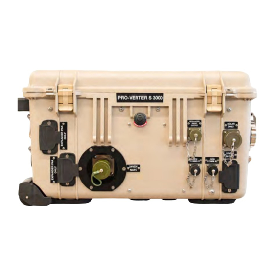
Page 24: Pro-Verter S 3000 Ags Description Pro-Verter Connection Ports And Vents
Operator and Maintenance Manual for the PRO-Verter S 3000 PRO-Verter S 3000 AGS Description PRO-Verter Connection Ports and Vents REGULATED 28VDC OUTPUT Description Connector Voltage Amps A 24 VDC In/Out Inter-Connect Port 24 VDC B 24 VDC NATO Slave (unmetered) -
Page 25: Figure 6. Pro-Verter Right Side
Operator and Maintenance Manual for the PRO-Verter S 3000 Description Connector Voltage Amps A 120 VAC Generator Input Connection Marinco B 120 VAC Grid Input Connection HBL61CM65 C Exhaust Vent Cover Figure 6. PRO-Verter right side Description Connector Voltage Amps... -
Page 26: Pro-Verter Faceplate
User Interface – The user interface is used to program and control the PRO-Verter and to monitor System status. The PRO-Verter is programmed at Solar Stik to meet the specifications of a specific application. Programming mode can be accessed if reprogramming is required. Contact Solar Stik Technical Support. - Page 27 Solar Stik Technical Support for further information. SD Card Port – An SD card must be installed for PRO-Verter to log data. This is an optional function. A dummy SD card is installed prior to shipment from Solar Stik. ®...
-
Page 28: Pro-Verter I-Plate
Operator and Maintenance Manual for the PRO-Verter S 3000 PRO-Verter I-Plate The I-Plate is a custom part of the PRO-Verter S 3000 and contains essential HPS setup, operation, and safety information for the System the PRO-Verter is integrated into. Figure 9 provides an example for such a System. -
Page 29: Operator Instructions
OPERATOR INSTRUCTIONS 1 Minimize Potential for Water and Dust Intrusion ALL Solar Stik equipment is designed for operation in adverse conditions; however, certain rules apply: 1 If operating in wet environments, use common-sense placement to avoid water intrusion by either flooding or precipitation. -
Page 30: How To Connect System Components To Pro-Verter
Operator and Maintenance Manual for the PRO-Verter S 3000 2 How to Connect System Components to PRO-Verter Example Power Generation Energy Storage Saft 6T Batteries 1 kW Generator with 1 kW Generator with Auto-Start/Stop Auto-Start/Stop Inter-Connect Strip 7 Power Management... -
Page 31: How To Connect Pro-Verter To Energy Storage Modules
Operator and Maintenance Manual for the PRO-Verter S 3000 a How to Connect PRO-Verter to Energy Storage Modules Note: A variety of energy storage modules (ESMs) may be connected to the PRO-Verter. Never mix battery chemistries in a System. More than two (2) EMSs Use 5’... -
Page 32: How To Connect Pro-Verter To Ac Power Source(S)
PRO-Verter S 3000. • Grid Power Cable: Connect AC power from the grid to the “AC Input” port on the right-hand side of the PRO-Verter S 3000. A custom cable may be required, depending on the grid power outlet. fuel-powered... -
Page 33: How To Connect Pro-Verter To Generator Comms Cables
Connect ONLY to Gen Comm #1 port on the front of the PRO-Verter and the Auto Generator Control port on the TQG using the 25’ TQG Gen Comm Cable. A Solar Stik Remote-start Enabling Kit (RsEK) must be installed on a TQG to communicate with the PRO-Verter. -
Page 34: Defender 1 Kw And Ranger 2 Kw Mpgs
Operator and Maintenance Manual for the PRO-Verter S 3000 ii Defender 1 kW and Ranger 2 kW MPGs Use Gen Comm ports #1 and/or #2 on the front of the PRO-Verter and the communication port on the generator using the 25’ Ranger/Defender Gen Comm Cable. -
Page 35: How To Connect Two (2) Mpgs In Parallel To The Pro-Verter
How to Connect two (2) MPGs in parallel to the PRO-Verter The PRO-Verter S 3000 has the ability to receive power from two (2) MPGs simultaneously. The power output from each of two generators is merged into a single “Y” cable connected to a single power input port on the left side of the PRO-Verter (Figure 12). -
Page 36: How To Connect Pro-Verter To Power Hub 3500
Operator and Maintenance Manual for the PRO-Verter S 3000 d How to Connect PRO-Verter to Power Hub 3500 Use a 5’ Inter-Connect Cable (A) to connect the PRO-Verter to the Power Hub 3500 using the ports illustrated in Figure 17. -
Page 37: How To Connect Power Hub 3500 To Pdm 3000
Operator and Maintenance Manual for the PRO-Verter S 3000 e How to Connect Power Hub 3500 to PDM 3000 Use an Inter-Connect Cable (A) to connect the Power Hub 3500 to the PDM 3000 using the ports illustrated in Figure 18. The Inter-Connect ports on the left front of the Power Hub are equal; use either one. -
Page 38: How To Connect Pro-Verter To 120 Vac Loads
Connect loads that require regulated 28 VDC output. The maximum output from this connection is 7.8 A or 220 W. A custom cable is required; contact Solar Stik for details. Turn off load power switches to prevent them from drawing power during System setup. Do not attempt to power the PDU or Tower from this connection. -
Page 39: How To Connect Pv Array(S) To Pro-Verter
Operator and Maintenance Manual for the PRO-Verter S 3000 h How to Connect PV Array(s) to PRO-Verter Connect the PV array(s)/Solar Cable to the PRO-Verter Solar Only port on the front of the PRO- Verter. Note: PV arrays up to 880 W can be connected to the PRO-Verter*. -
Page 40: How To Set Pro-Verter Date And Time
Operator and Maintenance Manual for the PRO-Verter S 3000 i How to Set PRO-Verter Date and Time The date and time format is Year/Month/Day Hour:Minute (24-hour clock). Note: Password is not required for setting this parameter. Home Screen Set PRO-Verter clock... -
Page 41: How To Program Pro-Verter To Match Ac Source Output Current
Press Down button to arrive at Input Setting. Press Enter button. Select Parameter The PRO-Verter S 3000 uses battery voltage to initiate generator start and stop functions. In a INPUT SETTING Press Down button to arrive at Grid Max Current. -
Page 42: Starting A Generator With Pro-Verter
Operator and Maintenance Manual for the PRO-Verter S 3000 k Starting a Generator with PRO-Verter 1 Toggle Generator Control switch(es) to the On position to start generator(s). Once generator has run for two (2) minutes, AC input should be qualified. -
Page 43: Pro-Verter Operating Modes
HPS with both AC and DC loads. AC loads connected to the PRO-Verter will not be supported if the AC power source connected to the PRO-Verter fails. Charge-only mode may be used in an HPS with DC-only loads. The PRO-Verter S 3000 has been programmed for charge- only mode per customer request ®... -
Page 44: Operating The Pro-Verter User Interface
Operator and Maintenance Manual for the PRO-Verter S 3000 Operating the PRO-Verter User Interface Figure 25. PRO-Verter user interface power and navigation buttons • On/Off Key—The On/Off key is used for switching on/off the PRO-Verter and also to enter/exit Standby mode. -
Page 45: Pro-Verter Status And Alarm Leds
Operator and Maintenance Manual for the PRO-Verter S 3000 PRO-Verter Status and Alarm LEDs The Status LED indicates the operating status of the PRO-Verter; the Alarm LED indicates a fault has occurred; specific information about the fault is reported on the user interface LCD screen. To clear faults see Clearing PRO-Verter Faults. -
Page 46: Pro-Verter Programmable Settings
Operator and Maintenance Manual for the PRO-Verter S 3000 PRO-Verter Programmable Settings Navigating “Select Group” and “Select Parameter” Menu Maps The Enter key is used to enter “Select Group” menu map from any operating mode screen. After the Enter key is pressed, the Up/Down keys are used to navigate to one of the seven (7) “Select Group”... -
Page 47: Parameter Groups: Pro-Verter Programmable Settings
Operator and Maintenance Manual for the PRO-Verter S 3000 Parameter Groups: PRO-Verter Programmable Settings “Parameter Groups” are the top-level categories of PRO-Verter programming. Table 4. Programmable Parameter Groups: Descriptions List of Parameter Groups 1 to 7 Parameter Description Group Name... -
Page 48: Charge Curve Programmable Settings
Operator and Maintenance Manual for the PRO-Verter S 3000 Please contact Solar Stik Technical Support before changing settings other than the clock or the AC Input settings. These settings are highlighted orange in the tables that follow. Charge Curve Programmable Settings Parameters in this group define System battery charging protocols. -
Page 49: Input Setting Programmable Settings
Operator and Maintenance Manual for the PRO-Verter S 3000 GROUP 1: CHARGE CURVE (Continued from previous page) Parameter Parameter Value Description 1 = lithium iron N/A. A CC/CV charging profile appropriate for LiFePO batteries has BATTERY TYPE phosphate been programmed. Do not change. -
Page 50: Input Low Limit Programmable Settings
Operator and Maintenance Manual for the PRO-Verter S 3000 Input Low Limit Programmable Settings Table 7. Parameters for Grid/Generator Input Low Voltage Level GROUP 3: INPUT LOW LIMIT Parameter Setting Value Description This is the reset voltage at which the PRO-Verter will revert to Charge mode Reset Voltage 105.0 V... -
Page 51: Other Functions Programmable Settings
Operator and Maintenance Manual for the PRO-Verter S 3000 Other Functions Programmable Settings Table 9. Power Saving/Alarm/Remote Switch/Multi-function Relay/etc. GROUP 5: OTHER FUNCTIONS Group Setting Value Description Power Saving 0 = Disable Enable or disable Power Saving mode when in Invert mode. -
Page 52: Saving/Uploading Programmed Parameters Saving Programmed Pro-Verter Parameters To Sd Card
Operator and Maintenance Manual for the PRO-Verter S 3000 Saving/Uploading Programmed Parameters Saving Programmed PRO-Verter Parameters to SD Card All the programmed parameters can be saved on an SD card (FAT 16/FAT 32 format, up to 16 GB capacity). The parameters will be saved in File named “xxxx_yyy.cfg”, where the first group of 4 digits xxxx is the model number of the inverter charger and the second group of 3 digits yyy is the Revision #. -
Page 53: Pro-Verter S 3000 Data Logging
Operator and Maintenance Manual for the PRO-Verter S 3000 PRO-Verter S 3000 Data Logging An SD card may be used to log operating information. When the SD card is inserted into the SD card slot, data logging is activated automatically (it will be disabled only if programmable setting has been changed to “0 = Disable”). - Page 54 Operator and Maintenance Manual for the PRO-Verter S 3000 The figure below shows an example of one of the file’s contents opened with a general purpose text reader. The second row shows data fields separated by semicolon (“;”). The third row onwards shows the status of the data fields at time interval equal to the programmed value of Data Log Time.
- Page 55 Operator and Maintenance Manual for the PRO-Verter S 3000 Text Import Wizard – Step 1 will be shown. Choose “Delimited” file type. Text Import Wizard – Step 2 will appear. Choose “Semicolon” and click Finish button. ® December 2020 Solar Stik , Inc.
-
Page 56: Troubleshooting Procedures
Operator and Maintenance Manual for the PRO-Verter S 3000 TROUBLESHOOTING PROCEDURES Clearing PRO-Verter Faults If any fault occurs, the user interface will display the fault message and the red “Fault” LED will be lighted. Remove cause of the fault. The unit will remain in Fault mode until the fault is cleared. -
Page 57: Pro-Verter Fault Messages And Troubleshooting Guides
Operator and Maintenance Manual for the PRO-Verter S 3000 PRO-Verter Fault Messages and Troubleshooting Guides Table 12. Fault Messages Symptoms and Troubleshooting Fault Messages and Troubleshooting Guide Fault Message Symptoms and Troubleshooting PRO-Verter is in Fault mode because the battery voltage has dropped to the set lower threshold of Batt Low Voltage. - Page 58 Operator and Maintenance Manual for the PRO-Verter S 3000 Fault Messages and Troubleshooting Guide Fault Message Symptoms and Troubleshooting The PRO-Verter is in Fault mode because the battery voltage has risen to the programmed upper threshold of Batt Over Voltage.
- Page 59 Operator and Maintenance Manual for the PRO-Verter S 3000 Fault Messages and Troubleshooting Guide Fault Message Symptoms and Troubleshooting The PRO-Verter is in Fault mode because of overload to the inverter: • There will be no AC output because the inverter will be switched off. The blue Status LED will be switched off and the red Fault LED will be steady on.
- Page 60 Operator and Maintenance Manual for the PRO-Verter S 3000 Fault Messages and Troubleshooting Guide Fault Message Symptoms and Troubleshooting The PRO-Verter is in Fault mode because the internal heat sink for the MOSFETS in the PRO-Verter has overheated to 158 ºF (70 °C).
-
Page 61: Figure 27. Fastener Locations On Vent Shroud (Upgraded/New Version)
Operator and Maintenance Manual for the PRO-Verter S 3000 MAINTENANCE, SECURITY, AND TRANSPORT 24VDC PRO-Verter S 3000 PMCS Table 13. 24VDC PRO-Verter S 3000-120 PMCS Item to be Item # Inspected Interval Procedures Non-mission Capable 1. Inspect case for visible damage... -
Page 62: Figure 29. Replacing Pro-Verter Filter (Left); Cleaning A Pro-Verter Filter (Right)
Operator and Maintenance Manual for the PRO-Verter S 3000 2 Remove and inspect the filter. Replace the filter if it is damaged (arrows in Figure 29). If the filter is in good shape, clean it by rinsing it with water to remove the particulate matter and dry it. -
Page 63: Figure 30. Steel-Reinforced Padlock Holes
Operator and Maintenance Manual for the PRO-Verter S 3000 Locking Component Cases to Prevent Tampering The Power Hub 3500 can be secured with a padlock to deter tampering. Four (4) latches allow the case to be sealed to prevent damage to the internal components from environmental factors. -
Page 64: Figure 32. Component Transportation: Wheels And Handles
Operator and Maintenance Manual for the PRO-Verter S 3000 Transporting Components The PRO-Verter has wheels and an extendible pull handle, enabling it to roll easily on appropriate surfaces. There are no transport restrictions for these components, which are safe for all modes of transportation, including land, sea, and air. - Page 65 Operator and Maintenance Manual for the PRO-Verter S 3000 24VDC PRO-Verter S 3000-120 EBA2 General Nominal Operating Voltage 24 VDC Input Battery Voltage Range 18.1 - 34 VDC Internal cooling Forced Convection User Interface 4-Line LED and buttons Case 1620 Pelican...
- Page 66 Operator and Maintenance Manual for the PRO-Verter S 3000 24VDC PRO-Verter S 3000-120 EBA2 Safety (1) 20 A Grid Input (1) 30 A Generator Input (2) 20 A AC Output Breaker(s) (1) 5 A USB Charger (1) 35 A Solar Input...
- Page 67 1 Solar Stik warrants, unless otherwise agreed to between buyer and seller (Solar Stik, Inc.), for a period of one (1) year from Solar Stik’s delivery of such Products, the Products shall be free from defects in materials and workmanship and shall conform to the contractual specifications or to specification sheet of the Product.
- Page 68 Operator and Maintenance Manual for the PRO-Verter S 3000 ® December 2020 Solar Stik , Inc. PRELIMINARY...
- Page 69 • Solar Stik New Equipment Training (on site) teaches Hybrid System configuration options with hands-on deployment of actual systems to enhance student understanding. Solar Stik Training Courses are tailored to the specific needs of the students. To schedule Solar Stik Training or to learn more about the curriculum, please contact us.
Need help?
Do you have a question about the PRO-VERTER S 3000 and is the answer not in the manual?
Questions and answers