Table of Contents
Troubleshooting

Related Manuals for Solar Stik 24VDC POWER HUB 3500


Summary of Contents for Solar Stik 24VDC POWER HUB 3500
- Page 1 OPERATOR AND MAINTENANCE MANUAL FOR THE 24VDC POWER HUB 3500 P/N 20-0302204 DISTRIBUTION STATEMENT A. Approved for public release; distribution is unlimited. Version 1.0 Interactive Updated: 20200130 January 2020 Solar Stik Inc.
-
Page 2: Table Of Contents
24VDC Power Hub 3500 Operator Manual Contents GENERAL INFORMATION, THEORY OF OPERATION, AND EQUIPMENT DESCRIPTION Power Hub Introduction . . . . . . . . . . . . . . . . . . . . . . . . . . . . . . . . . . . . . . . . . . . . . . . 5 Use of the Power Hub in a System . - Page 3 24VDC Power Hub 3500 Operator Manual Power Hub Internal Cooling ......... . . 27 Power Hub Internal Temperature Report .
- Page 4 Figure 1. A Power Hub in a Hybrid Power System ......................5 Figure 2. How a Power Hub works in a System ....................... 6 Figure 3. 24VDC Power Hub 3500 ........................... 7 Figure 4. Inter-Connect Plug ............................15 Figure 5. Overview of Power Hub connections ......................16 Figure 6.
-
Page 5: General Information, Theory Of Operation, And Equipment Description
24VDC Power Hub 3500 Operator Manual GENERAL INFORMATION, THEORY OF OPERATION, AND EQUIPMENT DESCRIPTION Power Hub Introduction The primary function of the DC Power Hub is to serve as a singular collection, management and distribution tool for DC power in a Hybrid Power System (HPS). -
Page 6: Use Of The Power Hub In A System
24VDC Power Hub 3500 Operator Manual Use of the Power Hub in a System The Power Hub provides a portal to integrate multiple DC power sources into a hybrid power network, including unregulated PV power and power from regulated sources (Figure 2). It funnels all incoming power to the batteries, PRO-Verters, or loads automatically, using basic programming in the User Interface to direct the flow. -
Page 7: Modes Of Operation
24VDC Power Hub 3500 Operator Manual Modes of Operation Depending on the application, there are several operational modes that can be configured using a Power Hub: • Hybrid DC loads, DC generation and batteries are all connected to a Power Hub. It is the central power management device in the system. -
Page 8: Safety Information Labels
Since the use of this manual and the conditions or methods of operation, use, and maintenance of this product are beyond the control of Solar Stik, this company does not assume responsibility and expressly disclaims liability for loss, damage, or expense—whether direct, indirect, consequential, or incidental—arising out of or anyway connected with such operation, use, or maintenance. -
Page 9: Fire Hazard
24VDC Power Hub 3500 Operator Manual Fire Hazard Fire Types Class A fire - Fires in ordinary combustibles such as wood, paper, cloth, trash, and plastics. Class B fire - Fires in flammable liquids such as gasoline, petroleum, oil, and paint. -
Page 10: Electric Shock Hazard
24VDC Power Hub 3500 Operator Manual Electric Shock Hazard WARNING Standing water around the electrical equipment and/or intrusion of water into the System components can increase the risk of electrical shock. DON’T LET THIS BE YOU! HIGH VOLTAGE: System components, PV arrays, and generators may have lethal line voltages. -
Page 11: Environmental And Handling Precautions
24VDC Power Hub 3500 Operator Manual Environmental and Handling Precautions All components are ruggedized, yet there are a few things the operator can do to prevent failures and prolong the operational life of the product. Water If outdoor operation is necessary, the lids of all components should be closed and latched whenever possible. -
Page 12: Theory Of Operation
24VDC Power Hub 3500 Operator Manual THEORY OF OPERATION Operation Overview The Power Hub has multiple DC connections on its exterior, allowing for multiple configuration possibilities. It requires connection to an active 24 V battery circuit in order for it to operate. A minimum of three (3) energy storage modules (i.e., Expander Paks) must be present and functioning for the Power... -
Page 13: Metered Circuits
24VDC Power Hub 3500 Operator Manual • The bayonet connector for the Solar Leash is keyed and unique to the PV circuit. It cannot be connected improperly, and no other System cable will fit. • The PV charge controller is fully protected against voltage transients, over-temperature, over- current, reverse battery connections, and reverse PV connections. -
Page 14: The Inter-Connect System
All of the individual Solar Stik components that operate in these categories utilize a unique connection architecture, known as the Inter-Connect Circuit. The Inter-Connect Circuit is the skeletal backbone of the Solar Stik System’s DC power network. It uses a simple, polarized, locking connection that is common throughout the architecture. All Solar Stik power management, energy storage, and power generation components are compatible with the Inter-Connect Circuit. -
Page 15: Figure 4. Inter-Connect Plug
24VDC Power Hub 3500 Operator Manual the affected leg will disconnect from the primary network, leaving the other circuits functioning. If a major failure occurs in the circuit, then the entire network will shut down. The Inter-Connect Plug Polarized •... -
Page 16: Equipment Description
24VDC Power Hub 3500 Operator Manual Equipment Description Connection Ports and Vents Port placards assist in making the correct connections between components. Please review the information on all of these plates and labels, as they contain the basic information required to set up and operate the Power Hub. -
Page 17: Figure 7. Right Side-Regulated 24 Vdc Input And Nato Connector
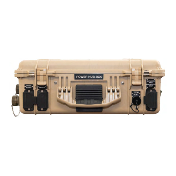
24VDC Power Hub 3500 Operator Manual Description Connector Amps Voltage A 24 VDC NATO Slave (unmetered) NATO Slave 24 VDC B Regulated 24 VDC Input Only (unmetered) Inter-Connect Port 100 total 24 VDC A. For connection to a tactical vehicle or generator. -
Page 18: Internal Cooling
I-Plate. The Warning and Notices are important lists of things to do and not to do. Be familiar with their content before operating the Power Hub. An I-Plate is (usually) tailored to a customer’s specific application. Contact Solar Stik Tech Support for details. Figure 10. Power Hub I-Plate... -
Page 19: Faceplate
The Faceplate provides support for the user interface and the Inter-Connect Cable storage ports. Recommended safety equipment, PV charging specifications, compatible battery chemistries, environmental operating conditions and Solar Stik Technical Support contact information are provided in the center of the Faceplate (Figure 11). -
Page 20: Operator Instructions
Power Hub simultaneously as long as their specifications meet the requirements shown on the Faceplate (Figure 10). The bayonet connector for the Solar Leash is keyed and unique to the Solar Stik System (Figure 7). It cannot be connected improperly, and no other Solar Stik System cable will fit. -
Page 21: Connecting A 24Vdc Pro-Verter Or 24 Vdc Expander Paks
24VDC Power Hub 3500 Operator Manual Connecting a 24VDC PRO-Verter or 24 VDC Expander Paks Connect the Power Hub to either a PRO-Verter or Expander Paks using the Expander Pak/PRO-Verter Only port on the right side (orange rectangle) of the Power Hub. -
Page 22: The Power Hub User Interface
24VDC Power Hub 3500 Operator Manual The Power Hub User Interface The user interface consists of an LCD screen and buttons for navigating Pages, Menu, and submenu items. Using the buttons and navigating the contents is simple and highly intuitive. -
Page 23: Menu Button
24VDC Power Hub 3500 Operator Manual Battery Icon: Reports battery SOC, voltage, and net current to/from the System battery. The SOC may be reported as “--” until the System batteries cycle enough to “learn” how to calculate accurately the SOC. Net battery current is the sum of all chargers and loads connected to the System batteries. -
Page 24: Monitoring Pv Power: Current And Historical
24VDC Power Hub 3500 Operator Manual Monitoring PV Power: Current and Historical Press the Menu button one time to display the device list. The window that will appear is illustrated below. Solar Charger #1 and #2 will appear in lines 2–3. Use the Up/Down navigation buttons to highlight the any of the solar chargers. -
Page 25: Monitoring System Batteries: Current And Historical
24VDC Power Hub 3500 Operator Manual Monitoring System Batteries: Current and Historical Press the Menu button one time to display the device list. The window that will appear is illustrated below. The Battery Monitor will be the first device listed. Values for the current battery SOC, DC bus voltage, and current (amps) will appear in the fields on that line. -
Page 26: Battery Monitor: Understanding Reported Values
24VDC Power Hub 3500 Operator Manual Battery Monitor: Understanding Reported Values The voltage and current flowing out of the Power Hub (reported in the Battery Monitor submenu) are accurate in any System configuration. The SOC reported by the battery monitor is accurate when both batteries and loads are connected directly to the Power Hub as shown in Figure 20. -
Page 27: Heat And Derating
24VDC Power Hub 3500 Operator Manual Heat and Derating The function and efficiency of all electronic equipment is related to and dependent upon the temperature at which it is operating. All equipment performs optimally within a narrow temperature range and less so as the temperature exceeds the upper end of that range. PV panel output drops off significantly in high heat as well. -
Page 28: User Interface Settings Menus
24VDC Power Hub 3500 Operator Manual User Interface Settings Menus Settings are accessed from the device list. The settings menus contain several parameters that may need to be changed during the course of normal operation. Many of the options are not relevant to the Power Hub. - Page 29 24VDC Power Hub 3500 Operator Manual VRM online portal Time Settings (Part 2) Time Enabled Logging enabled > General XXXXXXXXX VRM Portal ID > Firmware > 15 min Log interval > Date & Time Last contact > Remote Console Internal storage Storage location >...
-
Page 30: Power Hub Stacking
24VDC Power Hub 3500 Operator Manual Power Hub Stacking All Solar Stik Systems are scalable, and the method used for scaling Power Management components is “Stacking”. Multiple Power Hubs can be stacked when conditions warrant. Stacking can be used when a greater contribution from PV is desired, and the PV rating exceeds the ability of a single Power Hub to regulate. -
Page 31: Storing The Inter-Connect Cable
24VDC Power Hub 3500 Operator Manual Storing the Inter-Connect Cable The 5’ Inter-Connect cable can be coiled and stored using the connector on the Faceplate. Note: These connectors are not electrically active. Figure 24. Inter-Connect Cable storage Locking Component Cases to Prevent Tampering The Power Hub 3500 can be secured with a padlock to deter tampering. -
Page 32: Transporting The Power Hub
24VDC Power Hub 3500 Operator Manual Transporting the Power Hub The Power Hub transports like a briefcase and is safe for all modes of transportation, including land, sea, and air. There are no transport restrictions. Water Intrusion Remediation If water intrusion is suspected, and the System is still functional, disconnect power sources entering the Power Hub from the most distant location possible, power down the System (turn off the power switches on all of the System components) and then disconnect the Power Hub from the System. -
Page 33: Troubleshooting Procedures
24VDC Power Hub 3500 Operator Manual TROUBLESHOOTING PROCEDURES Power Hub Will Not Power Up If the Power Hub 3500 is not powered up, it probably is not connected to an active 24 VDC battery and/or there is no PV input. The LCD user interface will power up and be navigable when connected to either of these power sources. -
Page 34: Data Logging And Remote Monitoring
24VDC Power Hub 3500 Operator Manual Data Logging and Remote Monitoring Performance and Troubleshooting The Power Hub user interface monitors and reports Power Hub-,PV-, and battery-related data in real time. These data are also stored in the user interface and provide a historical record of these events over time. -
Page 35: Microsd Card Formatting
24VDC Power Hub 3500 Operator Manual When the storage device is full, no more data will be logged. This is due to the nature of Sqlite (a software library and file type) files. Removing data from the Sqlite database doesn’t free up usable disk space, and because of internal fragmentation, it doesn’t guarantee more data storage. - Page 36 24VDC Power Hub 3500 Operator Manual Step 1 . Create a user account 1. Go to https://vrm.victronenergy.com. 2. Click ‘Register for Free’. 3. Complete all the requested information. 4. A confirmation email will arrive to the registered account with a link to activate your account.
-
Page 37: Solar Charge Controller Error Codes
24VDC Power Hub 3500 Operator Manual Solar Charge Controller Error Codes Detailed error codes can be read with a LCD user interface. The vast majority of these errors will not be encountered when the Power Hub is operating in concert with other HPS components. All possible error codes are included for reference purposes. - Page 38 24VDC Power Hub 3500 Operator Manual Err 21 - Current sensor issue This error will not auto-reset. Disconnect all wires, and then reconnect all wires. Also, make sure the minus on the MPPT solar charge controller (PV minus/Battery minus) is not bypassing the solar charge controller.
- Page 39 24VDC Power Hub 3500 Operator Manual Information 65 - Communication warning Communication with one of the paralleled controllers in the Power Hub was lost. To clear the warning, cycle the power to the Power Hub. Information 66 - Incompatible device The controller is being paralleled to another controller that has different settings and/or a different charge algorithm.
-
Page 40: Maintenance Instructions
24VDC Power Hub 3500 Operator Manual MAINTENANCE INSTRUCTIONS Preventive Care and Maintenance Note: The function and efficiency of all electronic equipment is related to and dependent upon the temperature at which it is operating. It performs optimally within a narrow temperature range and less so as the temperature falls outside of that range. -
Page 41: Supporting Information
24VDC Power Hub 3500 Operator Manual SUPPORTING INFORMATION Using the Power Hub to Monitor PV Array Performance Failure of a single PV panel or array may not be noticed during normal operation if monitoring only the total/cumulative solar output current from multiple arrays in the pages menu of the LCD user interface. -
Page 42: Specifications
24VDC Power Hub 3500 Operator Manual To identify suspect arrays responsible for the decrease in current in that charge unit: • Disconnect all but one PV array and view the performance metrics reported by the user interface. • Cycle each PV array onto the Hub at the same connection, making note of the performance for each panel. -
Page 43: About Solar Stik, Inc
Solar Stik New Equipment Training (on site) teaches Hybrid System configuration options with • hands-on deployment of actual systems to enhance student understanding. Solar Stik Training Courses are tailored to the specific needs of the students. To schedule Solar Stik Training or to learn more about the curriculum, please contact us. Contact Technical Support Line 800-793-4364 Ext.
Need help?
Do you have a question about the 24VDC POWER HUB 3500 and is the answer not in the manual?
Questions and answers