
Related Manuals for Shuttle AK37GT


Summary of Contents for Shuttle AK37GT
- Page 1 AK37GT/AK37GTR SocketA AMD Athlon/Duron Processor Based DDR Main Board User's Manual...
- Page 2 The information contained in this manual is provided for general use by the customers. Trademarks Shuttle is a registered trademark of Shuttle Inc. VIA is a registered trademark of VIA Corporation. AMD, Athlon, and Duron are registered trademarks of AMD Corporation.
- Page 3 WARNING Thermal issue is highly essential for processors with a speed of 600MHz and above. Hence, we recommend you to use the CPU fan qualified by AMD or motherboard manufacturer. Meanwhile, please make sure CPU and fan are securely fastened well. Otherwise, improper fan installation not only gets system unstable but also could damage both CPU and motherboard because insufficient thermal dissipation.
-
Page 4: Table Of Contents
TABLE OF CONTENTS WHAT's IN THE MANUAL ..............5 Quick Reference ....................5 About This Manual ................... 5 1 INTRODUCTION ................6 1.1 TO DIFFERENT USERS ................6 First-Time DIY System Builder ..............6 Experienced DIY User ................6 System Integrator ..................6 1.2 ITEM CHECKLIST .................. - Page 5 3.2 JUMPER SETTINGS ................. 24 JUMPER & CONNECTOR GUIDE............25 Jumpers Clear CMOS (JP1) ................28 BIOS Write Protection (JP2) ..............29 Back-Panel Connectors PS/2 Keyboard & PS/2 Mouse Connectors ..........30 LAN Port Connectors ................30 USB1/USB2 Port Connectors ..............30 Parallel Port Connector ................
- Page 6 Other Connectors ATX Power Supply Connector (ATX1) ............ 37 Cooling FAN Connectors for CPU FAN (FAN1), AGP FAN (FAN2), SYSTEM FAN (FAN3) & North Bridge (FAN4) FAN ........ 38 IR Connector (JP3) ................38 Wake-On-LAN Connector (WOL1) ............39 Audio Connector CD_IN (J2/J3)............. 39 Audio Connector AUX_IN (J4) ...............
- Page 7 5 BIOS SETUP ................... 52 5.1 ENTER THE BIOS ..................52 5.2 THE MAIN MENU ..................53 STANDARD CMOS FEATURES ............... 55 ADVANCED BIOS FEATURES ..............59 ADVANCED CHIPSET FEATURES ............63 INTEGRATED PERIPHERALS ..............68 POWER MANAGEMENT SETUP .............. 72 PNP/PCI CONFIGURATION...............
-
Page 8: What's In The Manual
WHAT's IN THE MANUAL Quick Reference Hardware Installation >> Step-by-Step ..........Page 11 Jumper Settings >> A Closer Look ............Page 24 Software Utility >> How to Install ............Page 44 BIOS Setup >> How to Configure ............Page 52 About This Manual For First-Time DIY System Builder ............ -
Page 9: Introduction
Experienced DIY User Congratulate on your purchase of the AK37GT/AK37GTR mainboard. You will find that installing your new AK37GT/AK37GTR mainboard is just easy. Bundled with an array of onboard functions, the highly-integrated AK37GT/ AK37GTR mainboard provides you with a total solution to build the most stable and reliable system. -
Page 10: Item Checklist
1.2 Item Checklist Check all items with you AK37GT/AK37GTR mainboard to make sure nothing is missing. The complete package should include: - One piece of AK37GT/AK37GTR V1.3 Mainboard - One piece of Audio Cable (Central/Bass Channel) - One piece of ATA 133/100/66 Ribbon Cable... - Page 11 - One piece of Bundled CD-ROM with containing: Ø AK37GT/AK37GTR user's manual saved in PDF format Ø IDE RAID user's manual saved in PDF format (AK37GTR only) Ø VIA 4-IN-1 driver Ø AC97 driver Ø IDE RAID driver and Utility (AK37GTR only) Ø...
-
Page 12: Features
2 FEATURES AK37GT/AK37GTR mainboard is carefully designed for the demanding PC user who wants high performance and maximum intelligent features in a compact package. 2.1 Specifications - CPU Support Support Socket462 package CPU. AMD Athlon Processor with 200/266 MHz FSB... - Page 13 - I/O Interface Provides a variety of I/O interfaces: Ø 1 x Floppy interface for 3.5-inch FDD with 720KB, 1.44MB, or 2.88MB format or for 5.25-inch FDD with 360K or 1.2MB format. Ø 1 x PS/2 mouse connector. Ø 1 x PS/2 Keyboard connector. Ø...
- Page 14 - Advanced Configuration and Power Interface Features four power saving modes: Snoop, Suspend to RAM, Suspend to Disk, and Soft-Off. ACPI provides more efficient Energy Savings Features controlled by your operating system that supports OS Direct Power Manage- ment (OSPM) functionality. - System BIOS Provides licensed Award BIOS V6.0 PG on 2Mb Flash EEPROM and supports Green PC, Desktop Management Interface (DMI).
-
Page 15: Hardware Installation
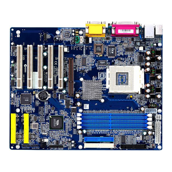
This section outlines how to install and configure your AK37GT/AK37GTR mainboard. Refer to the following mainboard layout to help you identify various jumpers, connectors, slots, and ports. Then follow these steps to guide you through a quick and correct instal- lation of your system. -
Page 16: Step 1 Install The Cpu
Step 1 Install the CPU: 1. Locate the CPU ZIF (Zero Insertion Force) socket on the upper-right sector of your mainboard (between the back-panel connectors and the DIMM memory slots). 2. Pull the CPU ZIF socket lever slightly sideways away from the socket to unlock the lever, and then bring it to an upwardly vertical position. -
Page 17: Step 2 Set Jumpers
Step 2. Set Jumpers This mainboard is jumperless! The default jumper settings have been set for the common usage standard of this mainboard. Therefore, you do not need to reset the jumpers unless you require special adjustments as in any of the following cases: 1. -
Page 18: Step 4 Install Internal Peripherals In System Case
Step 4 Install Internal Peripherals in System Case Before you install and connect the mainboard into your system case, we recommend that you first assemble all the internal peripheral devices into the computer housing, including but not limited to the hard disk drive (IDE /HDD), floppy disk drive (FDD), CD-ROM drive, and ATX power supply unit. -
Page 19: Step 5 Mount The Mainboard On The Computer Chassis
Step 5 Mount the Mainboard on the Computer Chassis 1. You may find that there are a lot of different mounting hole positions both on your computer chassis and on the mainboard. To choose a correct mounting hole, the key point is to keep the back-panel of the mainboard in a close fit with your system case, as shown below. -
Page 20: Step 6 Connect Front-Panel Switches/Leds/Speaker/Usb
Step 6 Connect Front-Panel Switches/LEDs/Speaker/USB connectors You can find there are several different cables already existing in the system case and originating from the computer's front-panel devices (HDD LED, Power LED, Reset Switch, PC Speaker, or USB devices etc.) These cables serve to connect the front-panel switches, LEDs, and USB connectors to the mainboard's front-panel connectors group (JP7 and USB2), as shown below. -
Page 21: Step 7 Connect Ide, Ide Raid (Ak37Gtr Only), And Floppy Disk Drives
Step 7 Connect IDE, IDE RAID (AK37GTR only), and Floppy Disk Drives 1. IDE cable connector 2. FDD cable connector 3. IDE RAID cable( Serial ATA) connector (AK37GTR only) RAID2 IDE4 RAID1 IDE3 - 18 -... -
Page 22: Step 8 Connect Other Internal Peripherals
Step 8 Connect Other Internal Peripherals 1. CD_IN, AUX_IN, TAD_IO and Bass/Center_Out connectors CD_IN CD_IN AUX_IN TAD_IO BASS 2. IR connector - 19 -... -
Page 23: Step 9 Connect Power Supply
Step 9 Connect Power Supply 1. System power connector ATXPWR ATX1 Step 10 Install Add-on Cards in Expansion Slots 1. Accelerated Graphics Port (AGP) Card 2. PCI Card - 20 -... -
Page 24: Step 11 Connect External Peripherals To Back-Panel
Step 11 Connect External Peripherals to Back-Panel You are now ready to put the computer case back together and get on to the external peripherals connections to your system's back-panel. 1. PS/2 Mouse and PS/2 Keyboard 2. LAN Port 3. USB1/2 Ports 4. -
Page 25: Step 12 First Time System Boot Up
Step 12 First Time System Boot Up To assure the completeness and correctness of your system installation, you may check the above installation steps once again before you boot up your system for the first time. 1. Insert a bootable system floppy disk (DOS 6.2x, Windows 95/98/NT, or others) which contains FDISK and FORMAT utilities into the FDD. -
Page 26: Step 13 Install Driver & Software Components
2000/ME/NT operating systems only. Make sure your operating system is already installed before running the drivers installation CD-ROM programs. 1. Insert the AK37GT/AK37GTR bundled CD-ROM into your CD-ROM drive. The auto-run program will display the drivers main installation window on screen. -
Page 27: Jumper Settings
3.2 Jumper Settings Several hardware settings are made through the use of jumper caps to con- nect jumper pins to the mainboard. Pin #1 could be located at any corner of each jumper; you just find a location marked with a while right angle, which stands for pin1#. -
Page 28: Jumper & Connector Guide
Jumper & Connector Guide Use the mainboard layout on page 11 to locate CPU socket, memory slots, expansion slots, jumpers and connectors on the mainboard during installation. The following list will help you identify jumpers, slots, and connectors along with their assigned functions: B2~B3 B4~B6 B7~B9... - Page 29 Jumpers : Clear CMOS : BIOS Boot block protection Back-Panel Connectors : PS/2 Keyboard : PS/2 Mouse : RJ45 LAN Port : 2 x USB (Universal Serial Bus) ports COM1/2 : Serial Port 1/2 (DB9 male) PRINTER : Parallel Port (DB25 female) LINE-OUT : Line-Out Port LINE-IN...
- Page 30 Other Connectors: ATX1 : ATX Power (20-pin header) FAN1 : CPU Fan Power FAN2 : AGP Fan Power FAN3 : System Fan Power : IR Connector : Wake-On-LAN Connector J2/J3 : CD_IN connector : Auxiliary_IN Connector : TAD_IN Connector : Bass/Center_Out Connector : Front-Panel Audio Connector : SPDIF Ext.
-
Page 31: Jumpers Clear Cmos (Jp1)
Jumpers Clear CMOS (JP1) JP1is used to clear CMOS data. Clearing CMOS will result in the permanent erasing of previous system configuration settings and the restoration of original (factory-default) system settings. Pin 1-2 (Default) Pin 2-3 (Clear CMOS) Step 1. Turn off the system power (PC-> Off). Step 2. -
Page 32: Bios Write Protection (Jp2)
Step 1. Turn off the system power (PC-> Off). Step 2. Make sure of place jumper cap on JP5 pin 2-3. Step 3. Insert a bootable system floppy disk with AK37GT/AK37GTR BIOS and flashutility and then turn on your system to execute flash utility. -
Page 33: Back-Panel Connectors
Back-Panel Connectors PS/2 Keyboard & PS/2 Mouse Connectors Two 6-pin female PS/2 keyboard & Mouse connectors are located at the rear panel of the mainboard. Depending on the com- puter housing you use (desktop or tower), PS/2 Mouse the PS/2 Mouse connector is situated at the top of the PS/2 Keyboard connector when the mainboard is laid into a desktop, as op- posed to a tower where the PS/2 Mouse... -
Page 34: Com1/2 Connector
COM1/2 Port Connector This mainboard can accommodate one serial device on COM. Attach a serial device cable to the DB9 serial port COM at the back-panel of your computer. Line-Out Port Connector Line-Out is a stereo output port through which the combined signal of all internal and external audio sources on the board is output. -
Page 35: Midi/Game Port Connector
MIDI/GAME Port Connector The GAME port is a 15-pin female connector. This port can be con- nected to any IBM PC compatible game with a 15-pin D-sub connector. MIDI Instrument Connection You will need a MIDI adapter to connect a MIDI compatible instrument to the sound card. -
Page 36: Front-Panel Connectors Atx Power On/Off Switch Connector (Power On)
Front-Panel Connectors ATX Power On/Off Switch Connector (Power ON) The Power On/Off Switch is a momentary type switch used for turning on or off the system ATX power supply. Attach the connector cable from the Power Switch to the 2-pin (Power ON) header on the mainboard. Note : Please notice all the LED connectors are directional. -
Page 37: Green Led/Power Led Connector (Gled/Pled)
Green LED/Power LED Connector (GLED/PLED) This header is dual color LED function. Dual color LED function is defined by either Power LED or Green LED, the header can be in these states. The Green LED indicates that the system is currently in one of the power saving mode (Doze/Standby/Suspend). -
Page 38: Power Led Connector (Pled)
Power LED Connector (PLED) Attach the 3-pin Power-LED connector cable from the housing front-panel to the (PLED) header on the mainboard. The power LED stays light while the system is running. Hardware Reset Connector (RESET) Attach the 2-pin hardware reset switch cable to the (RESET) header. Pressing the reset switch causes the system to restart. -
Page 39: Internal Peripherals Connectors Enhanced Ide, Ide Raid (Ak37Gtr Only), And Floppy Connector
Internal Peripherals Connectors Enhanced IDE, IDE RAID (AK37GTR Only), and Floppy Connectors The mainboard features two 40-pin dual-channel IDE device connectors (IDE1/IDE2) providing support for up to four IDE devices, such as CD-ROM and Hard Disk Drives (H.D.D.) and features two 40-pin dual-channel IDE RAID device connectors (RAID1/RAID2) providing support for up to four IDE devices, such as Hard Disk Drives (H.D.D.). -
Page 40: Other Connectors Atx Power Supply Connector (Atx1)
Other Connectors ATX Power Supply Connector This motherboard uses 20-pin Pentium 4 standard ATX power header, and comes with another two headers. Another is ATX12V with 2X2-pin +12 VPC ATX power supply header. Please make sure you plug in the right direction. ATXPWR ATX1 A1:Plug this connector when you use on AGP pro card. -
Page 41: System Fan (Fan3) & North Bridge (Fan4) Fan
CPU, System, and Other Fan connectors - FAN1/2/3/4 The mainboard provides three onboard 12V cooling fan power connectors to support CPU (FAN1)/(FAN2), System (FAN3) or Other (FAN4) cooling fans. SENCE GND +12V FAN1 FAN1/FAN2 /FAN3with rotate sense. FAN1 FAN2 FAN2 FAN3 Note: Both cable wiring and type of plug may vary... -
Page 42: Wake-On-Lan Connector (Wol1)
Note: Before connect your IR device, please be sure each IR on board pin allocation is matchable with the pin of the IR device. Other wise, incorrect IR connection may do damage to your IR device. Step 1. Attach the 6-pin infrared device cable to J10. (Refer to the above diagram for IR pin assignment.) Step 2. -
Page 43: Audio Connector Aux_In (J4)
3=AGND 4=AUXR Audio TAD_IO Connector (J5) Port J5 can be used to connect a modem audio line to AK37GT/AK37GTR mainboard. Typically, you would use this connector when running the voice mail software on your system for audio input and output. -
Page 44: Audio Center/ Bass Connector (J6)
Audio Center/Bass Header (J6) E7 E8 J6 header can be used to connect the cable which attached to center/bass am- plified speakers. 4 3 2 1 Pin Assignments: 1=Center BASS 2=AGND 3=AGND 4=Bass Front-Panel Microphone and Line_out Header (J7) This header allows users to install auxiliary front-oriented microphone and line- out ports for easier access. -
Page 45: Spdif Ext. Header(J8)
SPDIF Ext Header (J8) Port J8 can be used to connect special device. Pin Assignments: SPDIF Ext. 1=+12V 2=+5V IT8705F 0115-BXA M3Q040 3=N/A 4=SPDIF-OUT 5=SPDIF-IN 1 6=GND 7=NA 8=NA 9=KEY 10=GND Extended one USB Connector Header (USB2/USB3) The headers are used to connect the cable attached to USB connectors which are mounted on front-panel or back-panel. -
Page 46: System Memory Configuration
3.3 System Memory Configuration The AK37GT/AK37GTR mainboard has four 184-pin DIMM slots that allow you to install from 64MB up to 4GB of system memory. Each 184-pin DIMM (Dual In-line Memory Module) Slot can accommodate 64MB, 128MB, 256MB, 512MB, and 1GB of PC1600/PC2100/PC2700/ PC3200 compliant 3V single (1 Bank) or double (2 Bank) side 64-bit wide data path DDR SDRAM modules. -
Page 47: Software Utility
F Install Mainboard Driver - Installing . F Manual - mainboard and IDE RAID . F Link to Shuttle Homepage- Link to shuttle website homepage. F Browse this CD - Allows you to see contents of this CD. F Quit - Close this CD. -
Page 48: Install Mainboard Software
4.2 Install Mainboard Software Insert the attached CD into your CD-ROM drive and the CD AutoRun screen should appear. If the AutoRun screen does not appear, double click on Autorun icon in My Computer to bring up Mainboard Software Setup screen. -
Page 49: Install Via 4-In-1 Driver
4.3 Install VIA 4-in-1 Driver Select using your pointing device (e.g. mouse) on the “Install VIA Driver” bar to install 4-in-1driver. Once you made your selection, a Setup window run the installation automatically. When the copying files is done, make sure you reboot the system to take the installation effect. -
Page 50: Install Audio Driver
4.4 Install Audio Driver Select using your pointing device (e.g. mouse) on the “Install Realtek Driver” bar to install audio driver. Once you made your selection, a Setup window run the installation automatically. When the copying files is done, make sure you reboot the system to take the installation effect. -
Page 51: Install Lan Driver
4.5 Install LAN Driver Select using your pointing device (e.g. mouse) on the “Install LAN Driver” bar to install LAN driver. Once you made your selection, a Setup window run the installation automatically. When the copying files is done, make sure you reboot the system to take the installation effect. -
Page 52: Install Ide Raid Driver And Utility(Ak37Gtr Only)
4.6 Install IDE RAID Driver and Utility (AK37GTR only) Select using your pointing device (e.g. mouse) on the “Install RAID Driver” bar. Cause the IDE RAID driver can't be setup automatically, please follow below instructions to complete the installation. Then click on "Install RAID Utility" bar to install IDE RAID Utility. Once you made your selection, a Setup window run the installation automatically. -
Page 53: Install Usb 2.0 Driver
4.7 Install USB 2.0 Driver Select using your pointing device (e.g. mouse) on the “Install USB 2.0 Driver" bar to install USB 2.0 driver. Once you made your selection, a Setup window run the installation automatically. When the copying files is done, make sure you reboot the system to take the installation effect. -
Page 54: View The User's Manual
4.8 View the User's Manual Insert the attached CD into your CD-ROM drive and the CD AutoRun screen should appear. If the AutoRun screen does not appear, double click on AutoRun icon in My Computer to bring up Mainboard Software Setup screen. -
Page 55: Bios Setup
5 BIOS SETUP AK37GT/AK37GTR BIOS ROM has a built-in Setup program that allows users to modify the basic system configuration. This information is stored in bat- tery-backed RAM so that it retains the Setup information even if the system power is turned off. -
Page 56: The Main Menu
5.2 The Main Menu Once you enter the AwardBIOS(tm) CMOS Setup Utility, the Main Menu will appear on the screen. The Main Menu allows you to select from several setup functions and two exit choices. Use the arrow keys to select among the items and press <Enter> to accept and enter the sub-menu. - Page 57 Integrated Peripherals Use this menu to specify your settings for integrated peripherals. Power Management Setup Use this menu to specify your settings for power management. PnP / PCI Configuration This entry appears if your system supports PnP / PCI. PC Health Status This entry shows the current system temperature, Voltage, and FAN speed.
-
Page 58: Standard Cmos Features
Standard CMOS Features The items in Standard CMOS Setup Menu are divided into 10 catego- ries. Each category includes no, one or more than one setup items. Use the arrow keys to highlight the item and then use the <PgUp> or <PgDn>... - Page 59 IDE Secondary Master Options are in its sub-menu. Press <Enter> to enter the sub-menu of detailed options. IDE Secondary Slave Options are in its sub menu. Press <Enter> to enter the sub-menu of detailed options. Drive A/Drive B Select the type of floppy disk drive installed in your system. Ø...
- Page 60 ****************************************************** IDE Adapters The IDE adapters control the hard disk drive. Use a separate sub-menu to configure each hard disk drive. IDE HDD Auto-Detection Press <Enter> to auto-detect HDD on this channel. If detection is successful, it fills the remaining fields on this menu. Ø...
- Page 61 Precomp Warning: Setting a value of 65535 means no hard disk. Ø Min = 0, Max = 65535 Landing zone Set the Landing zone size. Ø Min = 0, Max = 65535 Sector Number of sector per track. Ø Min = 0, Max = 255 ****************************************************** - 58 -...
-
Page 62: Advanced Bios Features
Advanced BIOS Features This section allows you to configure your system for basic operation. You have the opportunity to select the system's default speed, boot-up sequence, keyboard operation, shadowing, and security. Virus Warning Allows you to choose the VIRUS Warning feature for IDE Hard Disk boot sector protection. - Page 63 External Cache Most processors that can be installed in this system use external level 2 (L2) cache memory to improve performance. Leave this item at the default value for better performance. Ø The choice: Enabled or Disabled. CPU L2 Cache ECC Checking This item enables or disables ECC (Error Correction Code) error check- ing on the CPU cache memory.
- Page 64 Boot Up NumLock Status Selects power-on state for NumLock. Ø The choice: Off or On. Gate A20 Option This entry allows you to select how the gate A20 is handled. The gate A20 is a device used for above 1MByte of address memory. Initially, the gate A20 was handled via a pin on the keyboard.
- Page 65 Note: To disabled security, select PASSWORD SETTING at Main Menu, and then you will be asked to enter password. Do not type anything and just press <Enter>; it will disable security. Once the security is disabled, the system will boot, and you can enter Setup freely.
-
Page 66: Advanced Chipset Features
Advanced Chipset Features This section allows you to configure the system based on the specific features of the installed chipset. This chipset manages bus speeds and access to system memory resources, such as DRAM and the external cache. It also coordinates communications between the conventional ISA bus and the PCI bus. - Page 67 DRAM Timing This item allows you to select the value in this field, depending on whether the board using which kind of DDR DRAM. Ø The Choice: Manual, Auto By SPD, Turbo or Ultra. DRAM CAS Latency When synchronous DRAM is installed, the number of clock cycles of CAS latency depends on the DRAM timing.
- Page 68 Write Recovery Time This item allows you to select Write Recovery Time. Ø The Choice: 2T or 3T. DRAM twTR This item allows you to select the DRAM twTR. Ø The Choice: 1T or 3T. AGP & P2P Bridge Control Options are in its sub-menu.
- Page 69 AGP Master 1 WS Read When this item enabled, reading from the AGP (Accelerated Graphics Port) is executed with one wait state. Ø The Choice: Enabled or Disabled. DBI Output for AGP Trans AGP 8X transfer mode only. Select Dynamic Bus Inversion function Enable / Disable.
- Page 70 PCI Delay Transaction The chipset has an embedded 32-bit posted write buffer to support delay transactions cycles. Select Enabled to support compliance with PCI specification version 2.1. Ø The Choice: Enabled or Disabled. Memory Hole In order to improve performance, some space in memory can be reserved for ISA cards.
-
Page 71: Integrated Peripherals
Integrated Peripherals VIA OnChip IDE Device Options are in its sub-menu. Press <Enter> to enter the sub-menu of detailed options. OnChip IDE Channel0 The chipset contains a PCI IDE interface with support to two IDE chan- nels. Select Enabled to activate the primary IDE interface; select Disabled to deactivate this interface Ø... - Page 72 Primary/Secondary Master/Slave PIO The four IDE PIO (Programmed Input/Output) fields let you set a PIO mode (0-4) for each of the four IDE devices that the onboard IDE inter- face supports. Modes 0 through 4 provide successively increased performance. In Auto mode, the system automatically determines the best mode for each device.
- Page 73 SuperIO Device Options are in its sub-menu. Press <Enter> to enter the sub-menu of detailed options. Onboard FDC Controller Select Enabled if your system has a floppy disk controller (FDC) in- stalled on the system board and you want to use it. If you install add-on FDC or the system has no floppy drive, select Disabled in this field.
- Page 74 Game Port Address This item selects Game Port Address. Ø The choice: Disabled, 201, or 209. Midi Port Address This item selects Midi Port Address. Ø The choice: Disabled, 330 or 300. Midi Port IRQ This item selects Midi Port IRQ. Ø...
-
Page 75: Power Management Setup
Power Management Setup The Power Management Setup allows you to configure your system to most effectively saving energy while operating in a manner consistent with your own style of computer use. ACPI Function This item allows you to enable/disable the Advanced Configuration and Power Management (ACPI) Ø... - Page 76 User Define Allows you to set each mode individually. HDD Power Down=Disabled or 1min.~15min. Suspend Mode= Disabled or 1 min ~1 hr. Ø The choice: User Define, Min Saving, or Max Saving. HDD Power Down When this item enabled and after the set up time of system inactivity, the hard disk drive will be powered down while all other devices remain active.
- Page 77 Soft-Off by PWRBTN Pressing the power button for more than 4 seconds forces the system to enter the Soft-Off state when the system has "hung.". Ø The choice: Instant-off or Delay 4 Sec. Run VGABIOS if S3 Resume This item allows the system to initialize the VGABIOS from S3 ( Sus- pend to RAM ) sleep state.
- Page 78 HDD & FDD When HDD & FDD stays On, any activity from one of the listed system peripheral devices wakes up the system. Ø The choice: OFF or ON. PCI Master When PCI Master stays On, any activity from one of the listed system peripheral devices wakes up the system.
- Page 79 signals this by causing an IRQ to occur. When the operating system is ready to respond to the request, it interrupts itself and performs the service. When On mode exist, activity will neither prevent the system from going into a power management mode nor awaken it. IRQ3 (COM 2 ) IRQ4 (COM 1) IRQ5 (LPT 2)
-
Page 80: Pnp/Pci Configuration
PnP/PCI Configuration This section describes the configuration of PCI bus system. PCI or Personal Computer Interconnection is a system which allows I/O devices to operate at the speed CPU itself keeps when CPU communicating with its own special components. This section covers some very technical items, and it is strongly recommended that only experienced users should make any changes to the default settings. - Page 81 If you set this field to "manual" , choose specific resources by going into each of the sub-menu that follows this field (a sub-menu is pro- ceeded by a ">"). Ø The choice: Auto(ESCD) or Manual. IRQ Resources When resources are controlled manually, assign each system interrupt a type, depending on the type of device using the interrupt.
-
Page 82: Pc Health Status
PC Health Status Shutdown Temperature Select the combination of lower and upper limits for the system shut- down temperature, if your computer contains an environmental moni- toring system. If the temperature extends beyond either limit, the system shuts down. Ø The choice: Disabled, 60 C/140 F, 65 C /149... -
Page 83: Frequency/Voltage Control
Frequency/Voltage Control CPU Ratio Select This item allows the user to adjust CPU Ratio . Ø The choice: Default, x5.5, x6, x6.5, x7, x7.5, x8, x8.5, x9, x9.5, x10, x10.5, x11, x11.5, x12, x13 or x14. CPU Clock This item allows the user to adjust CPU Host Clock from 100MHz to 200MHz by 1MHz step. - Page 84 Auto Detect DIMM/PCI Clk This item allows you to enable/disable auto detection DIMM/PCI Clock. Ø The choice: Enabled or Disabled. Spread Spectrum This item allows you to enable/disable the spread spectrum modulation. Ø The choice: Enabled or Disabled. CPU Voltage default This item show CPU voltage is set by manufacturer prior to delivery.
-
Page 85: Load Fail-Safe Defaults
Load Fail-Safe Defaults When you press <Enter> on this item, you will get a confirmation dialog box with a message similar to: Load Fail-Safe Defaults (Y/N) ? N Pressing 'Y' loads the BIOS default values for the most stable, minimal performance system operations. Load Optimized Defaults When you press <Enter>... -
Page 86: Set Supervisor Password
Supervisor/User Password Setting You can set either supervisor or user password, or both of them. The differences between them are: Supervisor Password and User Password The options on the Password screen menu make it possible to restrict access to the Setup program by enabling you to set passwords for two different access modes: Supervisor mode and User mode. -
Page 87: Save & Exit Setup
Password Disable If you select System at Security Option of BIOS Features Setup Menu, you will be prompted in entering the password whenever the system is rebooted or you try to enter Setup. If you select Setup at Security Op- tion of BIOS Features Setup Menu, you will be prompted only when you try to enter Setup.
Need help?
Do you have a question about the AK37GT and is the answer not in the manual?
Questions and answers