Table of Contents
Advertisement
Quick Links
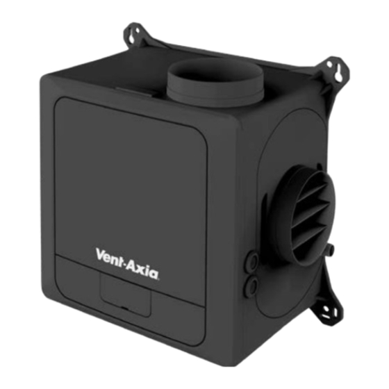
MultiVent Continuous Extract Ventilation
Thank you for purchasing this quality MultiVent continuous extract ventilation system.
To ensure correct function and safety, please read all instructions before using the product and keep all instructions for future reference.
SPECIFICATIONS
Duct
Fan Watts
(mm)
125mm & 150mm
SEC
Value
Class
Average
Warm
B
-26.9
-11.4
Compliance:
AS/NZS60335-2.80:2016
TYPICAL EXTRACTION LOCATIONS - BATHROOMS, TOILETS, LAUNDRIES, KITCHENS
The unit uses a highly efficient backward curved centrifugal motor
impeller set and is designed for continuous 24 hour use. Four settable
speeds can be configured to change these speeds based on an integrated
sensor or separate switch inputs (not supplied). The unit will run
at a normal flow rate until the humidity sensor or external switch input
trigger a speed change. In the case of the switched live and digital inputs,
the units will perform a step change in speed to the appropriate level.
In the case of the analog inputs and humidity sensor, the unit can be
programme to give a proportional response to the change in conditions.
The extracted air is replaced through natural air flow through the gaps
around doors and windows, trickle inlet slots, or best of all, the Manrose
Puro Filtered Passive Vent Kit (DCT4565) with typhoon cowl that has an
effective aerodynamic area of 3000mm
with the filter fitted.
Puro Filtered Passive Vent Kit DCT4565
Effective Aerodynamic Area
Supply
Max. Operating Temp
220-240V AC, 50Hz
40°C
Installation Instructions
sales@simx.co.nz | www.manrose.co.nz
When using electrical appliances, basic safety precautions should always
be followed to reduce the risk of fire, electrical shock and personal injury.
Max.
Max.
Fan Pressure
(W)
(Pa)
85
810
Control
Cold
Factor
-54.0
0.65
without the filter and 1400mm
2
with Filter
without Filter
IP Rating
IPX2
Specifications are subject to change without notice.
Description
MultiVent 3 Room Extract Unit Only
Important Note
– FAN7453 is a the MultiVent 3 Room Extract Unit ONLY.
Details in this Installation Instruction Manual give recommendations to how
the centralised extract unit can be combined with other components to make
it a complete system. See the comprehensive Manrose range of Duct and Grille
items to complete the installation.
The MultiVent continuous extract ventilation is designed for the simultaneous
ventilation of separate areas in the home and as a multipoint extraction system for
a wide range of commercial applications. The units can be wall, ceiling or loft mounted.
Where the ambient air has a high humidity content condensate drains are provided.
Free Air Fan Performance
(l/s)
(m
3
/hr)
159
572
Max.
Leakage Rates
Typology
Internal %
External %
Local
Demand
<5
<5
Control
2
1400mm
2
3000mm
2
Motor Housing
Impeller & Outer Rotor
Die Cast Aluminium
PBT Plastic
Minimum Specific
Performance
at 200 Pa
Fan Power
(l/s)
(W/l/s)
123
Annual Electricity
Consumption
(kWh/a)
Average
0.6
28.3
A
B
C
D
330
390
111
250
Weatherproof Cowl
150mm Stainless Steel
Product Code
FAN7453
Sound
dB(A)
0.14
52
Annual Heating Saved
(kWh/a)
Warm
Cold
12.8
55.4
E
ØF
96
125
Ducting
Aluminium Foil
Page 1
Distributed by Simx Limited
Advertisement
Table of Contents

Related Manuals for Vent-Axia MultiVent FAN7453


Summary of Contents for Vent-Axia MultiVent FAN7453
- Page 1 MultiVent Continuous Extract Ventilation Description Product Code MultiVent 3 Room Extract Unit Only FAN7453 Important Note – FAN7453 is a the MultiVent 3 Room Extract Unit ONLY. Details in this Installation Instruction Manual give recommendations to how the centralised extract unit can be combined with other components to make it a complete system.
- Page 2 MultiVent Continuous Extract Ventilation MULTIVENT CONTINUOUS EXTRACT VENTILATION SYSTEM INSTALLATION AND ELECTRICAL CONNECTION MUST BE CARRIED OUT BY A REGISTERED ELECTRICIAN CAUTION • Do not install this product where excessive oil or a grease laden atmosphere is or may be, present •...
-
Page 3: Installation
MultiVent Continuous Extract Ventilation INSTALLATION Position the unit, taking into consideration the position of the rooms to be ventilated, the exhaust position and the electrical services. Ensure there is adequate access for installation and maintenance. If the unit is sited in the heated void of the dwelling a condensate drain should not be necessary. When sited in a roof cavity, consideration should be given to fitment of a condensate drain. - Page 4 MultiVent Continuous Extract Ventilation INSTALLATION As per the picture above try to position the MultiVent fan housing in a location central to all of the rooms that you are planning to extract from. Also remember that the unit could create noise and should be mounted away from bedrooms. Mount the MultiVent using the 4 mounting points. Bear in mind that the exhaust (main extraction) is using 150mm aluminium foil ducting and a 150mm weather proof cowl.
- Page 5 MultiVent Continuous Extract Ventilation INSTALLATION • Mount the 125mm duct joiner (DCT0037) to the exhaust port of the MultiVent. • Fit the 150mm to 125mm reducer (DCT3239) to the 125mm duct joiner and tape both joints using the supplied duct tape. •...
-
Page 6: Electrical Connections
MultiVent Continuous Extract Ventilation ELECTRICAL CONNECTIONS 1. To remove the cover, use a coin or similar; depress the retaining tabs via the slots in the side of the unit. 2. With the power off, connect a suitable mains power cable (preferably to an existing lighting circuit) to the screw terminal block (L, N, Earth) connections. -
Page 7: Low Voltage Connections
MultiVent Continuous Extract Ventilation LOW VOLTAGE CONNECTIONS 1. Important: Use 4-core, low voltage, twisted pair, telecoms type cable for accessories. Accessories are connected via the IO (Input Output) PCB; see the Low Voltage Connections diagram in the Main fitting and wiring guide. Pos/Label Description Action RS485 communication to wired... -
Page 8: Feature Descriptions
MultiVent Continuous Extract Ventilation FEATURE DESCRIPTIONS Comfort Mode If Comfort mode is enabled the unit will behave as follows to all LS inputs Trigger Action LS input active less than 5 minutes No action (continue to run at Normal speed) LS input active more than 5 minutes but less Once LS input is removed, fan will run at user selected speed for the length than 20 minutes... -
Page 9: Unit Adjustment
MultiVent Continuous Extract Ventilation UNIT ADJUSTMENT 1. Commissioning and configuration on all products is supported by the 3 digit user interface and associated push buttons. 2. When powered on, the unit will display the firmware revision number, after a few seconds the unit will display the first option in the menu structure (see below). - Page 10 MultiVent Continuous Extract Ventilation COMMISSIONING – TYPICAL 3 ROOM SYSTEM In the following step we will provide an example of how to wire and control an MultiVent system hardwired to a Bathroom, Kitchen and Toilet. The MultiVent will utilize Humidity – Rapid Rise in its response and the 2 larger rooms (Bathroom and Kitchen) will also provide a PURGE speed function if these 2 rooms are switched on together.
-
Page 11: Fault Codes
MultiVent Continuous Extract Ventilation For the toilet the MultiVent will use its Extra Low Voltage connections for control. Using a short piece of wire connect a 0.5mm (or similar sized wire) from the GND terminal at the RS485 connection to the COM terminal adjacent to DIN 2 (digital input 2) + connector. Using a twin red TPS cable connect one RED core to the + connector at DIN 2 and connect the other RED core to the 5V terminal at the RS485 connection. - Page 12 MultiVent Continuous Extract Ventilation SPARE PARTS WARNING: THE FAN AND ANCILLARY CONTROL EQUIPMENT MUST BE ISOLATED FROM THE POWER SUPPLY DURING PART REPLACEMENT. Individual faulty parts should not be replaced due to complexity of assembly. Only the full scroll assembly is replaceable. To remove the scroll assembly, isolate the power, then use a coin or similar to depress the cover retention clips and remove the cover.
Need help?
Do you have a question about the MultiVent FAN7453 and is the answer not in the manual?
Questions and answers