Table of Contents
Advertisement
Quick Links
Advertisement
Table of Contents

Related Manuals for Chino AH4000


Summary of Contents for Chino AH4000
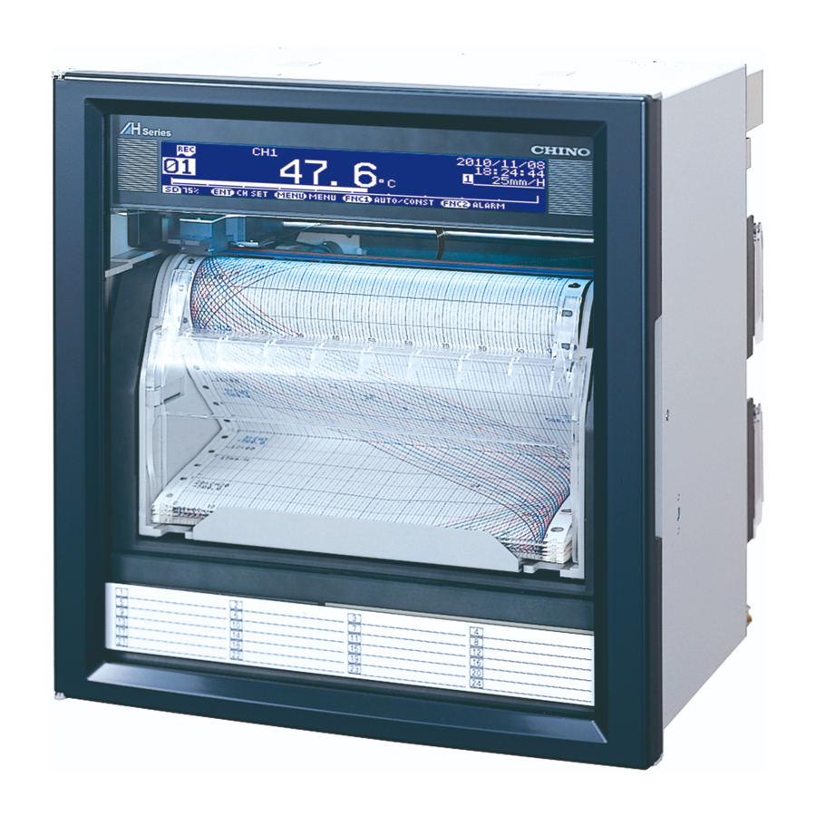
- Page 1 INST.No. INE-879E AH4000 (PEN TYPE) Hybrid Memory Recorder [ General ]...
-
Page 2: Table Of Contents
Table of contents 1. Introduction ........................1 2. For Safe Use ........................4 2-1. Preconditions for Use ............................4 2-2. Symbol Mark............................... 4 2-3. Label ................................... 4 2-4. Important Explanation ............................5 3. Model Code List ......................6 4. Mounting and Wiring ..................... 7 4-1. - Page 3 9-2. Recording Posotion (time) Adjustment ......................104 9-3. Input Adjustment “Inp Adj” ..........................105 9-4. Input Shift Adjustment ............................. 106 9-5. Wiring and Environment for Input Adjustment ....................107 10. Engineering Port (Mini-USB Terminal) ..............108 11. Troubleshooting....................... 109 11-1. Problems and Remedies ..........................
-
Page 4: Introduction
3. Replacement of parts or accessories that have reached the end of their life. Furthermore, the term ‘warranty’ in this sense covers only a CHINO’s product itself. Therefore, we are not responsible for compensation for whatever the damage that is triggered by failure of our product. - Page 5 Before use Make sure to check the following before use after unpacking the unit. If you have any question, please contact your dealer or our nearest office. 1. Exterior check Check that the appearance of the product has no damage. 2.
- Page 6 4. About attached chart paper For the unit, the chart paper No.EH01001 (0 to 100 equal divisions) is available and delivered. For the case that the chart paper is to be specified, various scales are available as follows. Chart Paper for Standard Scale Standard scale (linear) Chart paper No.
-
Page 7: For Safe Use
2. For Safe Use If the unit is used in a manner not specified by the manufacturer, the protection provided by the unit may be impaired. For safe use of the unit, please read and understand the following cautions. 2-1. Preconditions for Use The unit is a component type general product to be used mounted on an indoor instrumentation panel. -
Page 8: Important Explanation
7. Turn off the power supply if abnormality occurs Turn off the power supply immediately and contact your local CHINO’s sales office if any abnormal odor, noise or any smoke occurs, or if this unit becomes high temperature that is too hot to be touched. -
Page 9: Model Code List
3. Model Code List □ □□□ □□□ AH47 Input point 1: 1 pen 2: 2 pen 3: 3 pen 4: 4 pen Communications N: None E: Ethernet R: RS232C A: RS422A/RS485 Q: RS232C + RS485 C: RS422A/RS485 + RS485 G: Ethernet + RS422A/RS485 + RS485 Alarm output + remote contacts 0: None 2: 2 mechanical relay 'a' contact alarm outputs... -
Page 10: Mounting And Wiring
4. Mounting and Wiring 4-1. External Dimensions 241 When alarm output/remote contacts unit and communication unit are added Unit: mm 4-2. Mounting (1) Use the recorder mounting on an indoor installed instrumentation panel. (2) Brackets can be attached to a panel of steel with thickness of 2 to 6mm or equivalent strength. - Page 11 (1) Insert the unit into the panel cutout from the front of the panel. (2) Screw lightly two provided mounting screws into the screw holes on left/right side (two locations in total) of the recorder. (3) Insert the hexagon heads of screws installed above into the round holes of brackets, (from the front) sliding them as shown in the figure, press it firmly against the panel, and tighten them with the provided wrench or a Phillips-head screwdriver.
-
Page 12: Wiring
4-3. Wiring 1. Terminal board diagram The figure below is the diagram of the terminal board with the option [Alarm relay output (12 points ‘a’ contact) + remote contacts (10 points) and communication interface]. - 9 -... - Page 13 The figure below is the diagram of the terminal board with the option [Alarm relay output (8 points ‘c‘ contact) + remote contacts (10 points) and communication interface]. - 10 -...
- Page 14 The figure below is the diagram of the terminal board with the option [Alarm relay output (2 points ‘a ‘contact) and communication interface]. - 11 -...
- Page 15 Alert symbol mark ( ) and location Mark is attached to the location to which if human body touches, an electric shock may be generated. Warning Terminal name Location of attached mark Power terminal Lower left of power terminal Measurement input terminal Upper left of terminal cover Mechanical relay ‘c’...
- Page 16 2. Precautions on wiring Precautions on wiring are described below. Observe them to maintain safety and reliability. Feed power source For the power source for the unit, use the single-phase power source with stable voltage and without waveform strain to prevent malfunctions. (1) Switch and overcurrent protective device Add a switch and overcurrent protective device (250V, 3A) to the feed power source to prevent an electric shock on wiring.
- Page 17 Use crimping terminals. (1) To prevent looseness or disconnection of terminals and short circuit between terminals, install crimping terminals to termination of connection cables. (2) To prevent an electric shock, use crimping terminals with insulation sleeves. Terminal Type and Termination Treatment Terminal board Termination treatment (Unit: mm) Diameter...
- Page 18 3. Power/protective conductor terminals wiring Power/protective conductor terminals Power terminal Protective conductor terminal 100 - 240V AC 50/60Hz 40 VA MAX Power (voltage, frequency, and power consumption) Turn OFF feed power source. Warning Before power/protective conductor terminals wiring, make sure to turn off the feed power source to prevent an electric shock.
- Page 19 4. Measurement input terminals wiring Caution Allowable input voltage Measurement input terminal Turn OFF the feed power source before Input type Allowable input voltage wiring to prevent an electric shock. Voltage, thermocouple input ±10VDC * Install crimping terminals with insulation Resistance thermometer input ±6VDC sleeves to input terminals for wiring.
- Page 20 Input unit terminal cover mounting/removing (1) Raise the cover to the direction of the arrow. (2) Turn to the direction of the arrow. (3) Pull it out to the direction of the arrow to remove. 5. Alarm output terminals wiring (option) Alarm output terminals The terminal configuration depends on the output specification.
- Page 21 Wiring Turn OFF the feed power source and the power source for buffer relay before wiring to prevent an electric shock. Use the cable of AWG20 to 16. (1) Wire the cable to the load via the buffer relay. (2) To the alarm output terminals, type O crimp style terminal with insulation sleeve which is connected to double insulated signal wire should be connected.
- Page 22 Precautions on wiring The following are precautions on wiring. Item Description Mechanical relay output Power supply Resistance load Inductive load specification contact (Minimum load) 100VAC capacity 100μA100mVDC 240VAC (Common to ‘a’ contact 30VDC and ‘c’ contact) Contact protective element Install the contact protective element which fits the buffer relay. Z installation ...
- Page 23 6. Remote contacts terminals wiring and operation selection (option) Only with remote contacts terminals (option). Remote contacts terminals Characteristics of contact Note input terminals Voltage on contact open: About 5V Upper row Current on contact short: About10mA Remote contacts terminals ■...
- Page 24 ON: Short-circuit OFF: Open Operation for which terminal No. is decided automatically Operation name Terminal contact signal 3 chart speed setting other than the setting here is required. (See 8-7. Chart Speed Settings.) Between COM and EX terminals Recording ON/OFF and 3 chart speed selection (1) 3 chart speed selection...
- Page 25 7. Communication I/F terminal wiring (partly option) AH4000 can be connected for communications with RS232C, RS422A, RS485, and Ethernet. terminals Communications terminal Ethernet connector Communications terminal type (option) RS232C RS422A COM1 Short with Short with RS485 COM2 RS485 * RS232C and RS422A/485 of COM1 are to be specified on purchase.
- Page 26 (2) RS422A Connection between a line converter and the unit Crimp type ring terminals ↔ Crimp type ring terminals RS422A cable Cable (for a line converter) (black) (black) (white) (white) (red) (red) (green) (green) (blue) (blue) Shape Line converter side Recorder side 4-core cable of twisted 2-core cables of twisted VCTF lines.
- Page 27 (3) RS485 Connection between the unit and other devices and between a line converter and the unit Cable Crimp type ring terminals ↔ Crimp type ring terminals RS485 cable RDA(black) (black)SA RDB(white) (white)SB SG(green) (green)SG Device side, Line converter side Recorder side Shape 2-core cable of twisted CVVS lines.
- Page 28 (2) RS422A wiring PC and multiple devices are connected with RS422A. A line converter is required. RS422A cable is within 1.2km of total extension and up to 31 devices can be connected. Install a resistor of 100Ω to the last edge of the transmission line device side. (General metal film resistors will be fine.
- Page 29 (4) Ethernet wiring Example of connection between PC and Ethernet devices (one-to-one connection) Crossover twist-pair cable with shield (Max.100m) PC side Device side Example of connection between PC and HUB/Ethernet devices (one-to-N connection) Straight twist-pair cable PC side with shield (Max.100m) Straight twist-pair cable with shield (Max.100m)
-
Page 30: Part Names
5. Part Names 5-1. Front Section of Internal Unit Power switch Open the display board same direction as the unit door. The power switch is located at the upper left of the unit. Display Enlarged view of power switch SD card Engineering port Operation/set keys slot... -
Page 31: Operation/Set Keys
5-2. Operation/Set Keys Status LED Lights in green while recording is ON. Recording is turned ON/OFF by the key. Flashes when chart ends. CARD Lights in green when SD card is recognized by the unit, or flashes in a recognition process. ... -
Page 32: Operation
6. Operation Note Handling of chart cassette 6-1. Preparation for Operation Be careful of injury by dropping the chart cassette after pulling it from inner unit. Take care not to catch your fingers in the unit when putting the chart cassette back. 1. - Page 33 2. How to set plotter pen and cartridge pen 1. Recording pen types Plotter pen Cartridge pen (1) There are two types of recording pens, the plotter pens for digital printing and cartridge pen for trace printing. (2) There are four kinds of cartridge pens for the 1 pen to the 4 pen.
- Page 34 4. Setting plotter pen 5. Setting cartridge pen Penholder Main Shaft Penholder Plotter pen Setting is completed (1) Insert the plotter pen into the penholder untill it stops. (Note) Incomplete insertion may result in recording troubles. (1) Push the arms of the cartridge pen into the (2) For removing of the plotter pen, pull it from the penholder as an angle shown in the figure.
-
Page 35: Basic Operation
6-2. Basic Operation 1. Power on Turn the power switch to ON while the chart cassette is in the housing. Data will be shown on the display after about 10 seconds. After detecting the initial position, the printer prints the date and time and then feeds chart about 5mm. Display backup Note 1 While recording is OFF... - Page 36 3. Switching of display The unit can provide seven display modes depending on the number of inputs. On 1-point display, 1-point + bar display, 2-point display and 2-point + bar display, either fixed or sequential display can be selected for each display mode (pressing the key switches the display between AUTO: sequential and CONST: fixed).
- Page 37 4. Chart recording operation “*** Quit recording? ***” Recording ON Pressing the key turns recording OFF. “*** Start Digital data printing? ***” Press the key to start. “*** Start recording? ***” Recording OFF Pressing the key turns recording ON. Any of the above settings can be cancelled by pressing the key.
- Page 38 Data printing Print numeric values of the latest measurement data as shown in the example below. Printing mode is different depending on the chart speed. When the chart speed is 1 to 499mm/H, trace printing is continued without interruption. Printing is done by synchronized with chart feeding.
- Page 39 Chart feed Chart can be fed using the key. While the key is pressed, chart is fed at a speed of 600mm/min. When fast-feeding chart, recording is stopped. Feed chart when a measurement target or measurement condition is changed. Reference Feeding chart Chart can be fed manually using the drum.
-
Page 40: Operation
6-3. Operation 1. Types and contents of chart recording There are two types of chart recording: trace printing and digital recording/printing. Without setting particular items, trace printing and fixed time printing are performed while recording is ON. Item Contents Trend printing is executed for each pen (channel). Trace printing (Cartridge pen) Green Blue... - Page 41 2. Fixed time printing interval When recording is ON at the time of power-on, fixed time printing is performed first. The following table shows printing intervals which vary depending on the printing item. Min/max chart record, channel number and Time and time line Chart speed tag and unit Varies depending on...
- Page 42 3. Restrictions on recording Digital recording/printing unavailable at certain chart speeds When chart speed is set to 150mm/H or higher, printing function besides time line, power-on time printing, data printing, list printing, setting change mark are disabled. Overlapping of digital recording/printing When the recording position is overlapped, printing may not be performed.
-
Page 43: Factory Default Settings
7. Factory Default Settings 7-1. List of Factory Default Settings Item Default value (1) Time Current time (year/month/date: Japan time) (1) Input type V : -50.00 to 50.00 (2) RJ None (2) Range (3) Chart printing -50.00 to 50.00 (3) Scale -50.00 to 50.00 (4) Unit (5) Tag... -
Page 44: Setting Method
8. Setting Method 8-1. Basic Rules The following provides general information on setting operations. Pressing the key can return to the measured value display from any window. 1. Setting items and parameters The unit offers various condition settings to allow users to obtain various recording results and data. Major items of measuring/recording conditions, such as range, scale and chart speed, are called “setting items”, whereas detailed items of each setting item are called “setting parameters”... - Page 45 7. Changing settings To change settings, move the cursor () located at the left of a setting parameter to the parameter to be set (changed). When the target parameter is selected by pressing the key, the set value will be highlighted and become settable.
-
Page 46: Input Type Settings "Range
8-2. Input Type Settings “Range” Parameters including range, RJ (internal/external switching of reference junction compensation), scale and unit can be set collectively for each channel. 1. Parameters Input Set the input type (INPUT), range (RANGE-L/H) and RJ internal/external (RJ) in accordance with the sensor to be connected (thermocouple or resistance thermometer) and the target measuring range. - Page 47 9) Input filter The input filter has a function to stabilize the measuring input. A CR filter is mounted in the measuring circuit. In addition, a software filter (called as “input filter”) for the “primary delay computation” is also installed to smooth slight variations of the measuring input. The value for the programming is corresponding to “Time constant: T”.
- Page 48 2. Parameter setting (1) Pressing the key displays the menu window (list of setting items). (2) Select “Range”. (Set contents of all channels will be displayed.) (3) Move the cursor to the target CH with the ▲/▼ keys and press the key.
- Page 49 [List of Range setting parameters] Parameter Function Default Set value INPUT Select input type V, MV, K, E, J, T, R, S, B, N, U, L, WWRe26, -50.00 to 50.00 WRe5-26, NiMo-Ni, Platinel2, PtRh40-20, Cr-AuFe, Au/Pt, Pt100, QPt100 (old Pt100), JPt100, Pt50, Pt-Co, UNUSED Select whether to use reference junction EXT (external), INT (internal)
-
Page 50: Alarm Settings "Alarm
8-3. Alarm Settings “Alarm” Various alarm points can be set for measured value of each channel. Up to four alarm points per channel can be set and the type of alarm (upper/lower, diff upper/lower, or rate-of-change upper/lower) can be set to each alarm point arbitrarily. Using the alarm settings, alarm printing, alarm display, status LED indication and relay output can be performed. - Page 51 Output Alarm condition (activation/reset) at each alarm point is output from the relay of the specified No. (alarm output terminal No.). This output is not performed initially because it is set to “-“ prior to shipment. Output relay can be specified arbitrarily for each channel and level (from No.1 to 12 relay: optional). When “99”...
- Page 52 3. Alarm type Alarm type can be selected from the following six types for each alarm point. Upper limit alarm (H) Alarm is activated when the measured value of specified channel reaches or exceeds an alarm value. Set value ··························· alarm value, deadband Activation condition ··············...
- Page 53 Rate-of-change alarm Differential alarm (Diff upper alarm) (Diff lower alarm) Upper alarm: Variation width per unit time [∆t] (PV2 - PV1) is at plus side. Difference (Absolute Lower alarm: Variation width per unit time [∆t] Difference value) (PV2 - PV1) is at minus side. (Absolute value) Alarm value of U...
- Page 54 4. Parameter settings Pressing the key displays the menu window (list of setting items). (2) Select “Alarm”. (3) Move the cursor to the target channel with the ▲/▼ keys and press the key. The cursor does not move to parameters other than CH.
- Page 55 [List of Alarm setting parameters] Parameter Function Default Set value Level Select level for setting 1 to 4 Mode Select alarm type None None, H (upper), L (lower), B (diff upper), S (diff lower), U (rate-of change upper), D (rate-of-change lower) Value Set alarm judgment value -30000 to 99999...
- Page 56 6. Checking alarm status You can check if alarm is activated on the measured value display window which is normally displayed. However, to check the detail of activated alarm (alarm type, level, etc.), press the key on the measured value display window to open the alarm status check window.
-
Page 57: Calculation Settings "Calc
8-4. Calculation Settings “Calc” Configure calculation settings to perform arbitrary calculation for each individual channel. Each calculation is performed at the same intervals as input. Data (including communications input) is processed according to the calculation settings except when the "calculation type (Kind)"... - Page 58 2. Channels specifying calculation For channels specifying calculation, data after processing the specified calculation is recorded or displayed. 3. Calculating max/min/avg value Calculation reset Calculation is reset automatically at specified intervals. Therefore the maximum, minimum and average values are calculated in each interval. Start time of calculation This is valid for the first calculation after setting only.
- Page 59 5. Parameter settings (1) Pressing the key displays the menu window (list of setting items). (2) Select “Calc”. (3) Move the cursor to the target channel with the ▲/▼ keys and press the key. The cursor does not move to parameters other than CH.
- Page 60 [List of Calc setting parameters] Parameter Function Default Set value Kind Select calculation type None None (No calculation), Root (square root), LOGe (natural logarithm), LOG10 (common logarithm), INT (integration), Humidity (humidity/temperature calculation) COM.Input (data communications input), MUL (arithmetic 1), DIV (arithmetic 2), High-Peak (max value), Low-Peak (min value), Average (average calculation), Power (exponent), ABS (absolute value calculation)
-
Page 61: Formula Settings "Formula
8-5. Formula Settings “Formula” Set a formula used when “Formula” is selected for Kind in "calculation settings". Up to 12 formulas, which are shared by all channels, can be registered using a character string consisting of 50 characters at maximum. 1. - Page 62 Channel data calculation functions Function calculation is performed. Symbol Example Note Input data CH(X) An error occurs when X: Channel No. Calculation result PCH(X) measured data contains Previous result OCH(X) Data at the last scan (0.1sec error data (±OVER, etc.). before) Integration ITG(X)
- Page 63 Normal integration Integration value is reset at every reference time and interval. Entering a formula ITG(X) X: Channel No. of integration target Calculation detail + {(PV + PV ) x (T )} ÷ 2 -T : Integration result : Last integration result : Integration target data : Last integration target data : Calculation time...
- Page 64 5. Dew-point temperature Entering a formula DEW(T#H) T: Channel No. of temperature data, H: Channel No. of relative humidity Dew-point temperature is obtained from the following calculation. t: Temperature data h: Relative humidity data D: Dew-point temperature (1) K = t + 273.15 (2) When t ≥...
- Page 65 8. First-order lag filter Entering a formula IIR(X#T) X: Data channel No., T: Time constant (x 0.1 sec) First-order lag filter calculation is processed on the channel X data. Calculation detail {dt ÷ (dt + t)} x (x – d) + d dt: Sampling time t: Time constant x: Current value of channel X...
- Page 66 11. Broken line approximation Entering a formula LIC(X#A) X: Data channel No. A: Defined broken line approximation table No. "Broken line approximation" can be added in a formula, and the first-order approximation can be performed for up to 30 broken lines. Broken line is defined separately using up to six tables, and the table No.
- Page 67 13. Parameter settings (1) Pressing the key displays the menu window (list of setting items). (2) Select “Formula”. (3) Move the cursor to the target formula No. with the ▲/▼ keys and press the key. The cursor does not move to parameters other than formula No.
-
Page 68: Broken Line Approximation Table Settings "Seg.tbl
8-6. Broken Line Approximation Table Settings “Seg.Tbl” Set the table used when “BrokenLine” is selected as calculation type. Up to six tables can be set, and up to 30 points can be set to each table. For channels selecting “BrokenLine” as calculation type, a table can be selected individually from six options. -
Page 69: Chart Speed Settings "Chart
8-7. Chart Speed Settings “Chart” Set the chart speed. When using remote contacts (optional), see also “13-1. External Operation Settings”. (1) Pressing the key displays the menu window (list of setting items). (2) Select “Chart”. (3) 3-speed setting is available only when using remote contacts (optional). -
Page 70: Time Axis Synchronization "Poc
1st pen, the stored data are printed. The printing except for the 1 pen are not executed at the real time, however there will be no time axis gaps the on the chart. Installation position for AH4000 Switching of time axis Reference... - Page 71 3. Parameter settings (1) Pressing the key displays the menu window (list of setting items). (2) Select “POC”. (3) Press key to enable settings then select set value. (4) After setting of this item is finished, move the cursor to (5) Press the key to register the settings (when chart recording is ON, a...
-
Page 72: Subtract Printing Settings "Sub Prt
8-9. Subtract Printing Settings “Sub Prt” Subtract printing can be set using either of the following method: (1) use channel C data as difference between channel A and channel B, or (2) use channel E data as difference between channel D and a reference value. Channels used for subtract printing are also used for normal measurement. - Page 73 2. Parameter settings (1) Pressing the key displays the menu window (list of setting items). (2) Select “Sub Prt”. (3) Move the cursor to the target channel with the ▲/▼ keys and press the key. The cursor does not move to parameters other than CH.
-
Page 74: Periodic (Data Interval) Data Printing Settings "Dataint
8-10. Periodic (Data Interval) Data Printing Settings “DataInt” In addition to the trace printing on a chart, measured data of each channel can be printed numerically. Measured data can be recorded or printed digitally at desired intervals. Select ON/OFF to enable or disable digital recording/printing for each channel (DIGI.REC) in input type settings described in “8-2. -
Page 75: Periodic (Specified Time) Data Printing Settings "Prttime
8-11. Periodic (Specified Time) Data Printing Settings “PrtTime” When the interval described in “8-11. Periodic (Data Interval) Data Printing Settings” is set to “00 : 00”, printing at specified time becomes effective. Time can be specified for up to 24 points and it can be set to ON/OFF individually. (1) Pressing the key displays the menu window (list of setting items). -
Page 76: List Printing Settings "Listprt
8-12. List Printing Settings “ListPrt” List printing is used to check the set contents. Contents to be printed depend on the list number. (1) Pressing the key displays the menu window (list of setting items). (2) Select “ListPrt”. (3) Press the key to make it available for setting and then select the list number. -
Page 77: Message Printing 1 Settings "Msgprt1
8-13. Message Printing 1 Settings “MsgPrt1” Example of message printing A message consisting of 15 characters at maximum can be printed and up to 20 types of message can be registered. It is also possible to print a registered message in conjunction with the calendar timer or remote contacts (calendar timer and remote contacts should be set separately). -
Page 78: Message Printing 2 Settings "Msgprt2
8-14. Message Printing 2 Settings “MsgPrt2” A message consisting of up to 72 characters is printed on a chart with arbitrary timing. Message is registered at the time of printing and the last registered message is shown on the setting window. (1) Pressing the key displays the menu window (list of setting items). -
Page 79: Recording Format Settings "Prtform
8-15. Recording Format Settings “PrtForm” Set the format for trace printing depending on the intended use. This function is provided to select the format used for trace printing. Input range and its accuracy are determined by the settings made in “8-2. Input Type Settings”. The recording format cannot be set for each individual channel. -
Page 80: Auto Range Settings "A.range
8-16. Auto Range Settings “A.Range” When “Auto Range” is selected for recording format, set the related items. There are two types of automatic range-shift: “Normal” and “Overlap”, the former has separate ranges and the latter has ranges overlapping each other partially around the lower/upper limit. - Page 81 * Make sure that the recording format is set to “Auto Range (automatic range-shift)” and then perform the following settings. (1) Pressing the key displays the menu window (list of setting items). (2) Select “A.Range”. (3) Move the cursor to the target channel with the ▲/▼...
-
Page 82: Compressed/Expanded Printing Settings "Cmp&Exp
8-17. Compressed/Expanded Printing Settings “Cmp&Exp” When “Comp. &Exp.Print” is selected for recording format, set the related items. A specified area within the chart recording range can be shrunk or expanded. • Individual setting available for channels. • Recording range can be set arbitrarily regardless of the setting of range/chart recording upper and lower limits. •... - Page 83 * Make sure that the recording format is set to “Comp.&Exp.Print (compressed/expanded printing)” and then perform the following settings. (1) Pressing the key displays the menu window (list of setting items). (2) Select “Cmp&Exp”. (3) Move the cursor to the target channel with the ▲/▼...
-
Page 84: Zone Printing Settings "Zoneprt
8-18. Zone Printing Settings “ZonePrt” When “ ” is selected for recording format, set the number of divisions and recording area. Recording area can be Zone Print divided into two to four, and you can select an area for recording. This is useful to avoid overlapping of recordings. ... - Page 85 * Make sure that the recording format is set to “Zone Print (zone printing)” and then perform the following settings. (1) Pressing the key displays the menu window (list of setting items). (2) Select “ZonePrt”. (3) Press the key. (4) Move the cursor to the parameter to be set with the ▲/▼//...
-
Page 86: Sd Card "Sd Card
Please note that CHINO holds no responsibilities for losses resulting from damage or data loss of SD card. Use SD card with 2GB or less memory and format to FAT16. Use CHINO’s SD card sold separately. When using except for provided SD card by CHINO (sold separately), data may be damaged and lost. - Page 87 4. Settings related to measured data save Set the format for recording measured data on SD card, trigger to start/stop recording and measuring interval. (1) Pressing the key displays the menu window (list of setting items). (2) Select “SD CARD”. (3) Make sure that the cursor is on Setting beside “Recording data-Saving”...
- Page 88 [List of Recording data-Saving setting parameters] Parameter Function Default Set value Format Select format for recording to SD Text Binary: Uses “A4F” extension. Analysis software is card required for data replay. Text: Uses “TXT” extension. Data can be replayed with Microsoft Excel as needed. Binary (float): Binary (floating decimal point) Text (float): Text (floating decimal point)
- Page 89 Note 5 File division Measured data file is divided by a certain number of bytes. (The number of bytes varies by the number of recording channels, etc.) Also, the file is divided if device setting or date and time setting is changed. Reference File save location A measured data file is saved in a folder created each year/month within the “HR_DATA”...
- Page 90 5. Saving setting parameters The setting data of the unit can be saved to an SD card. (1) Select “SD CARD” from the menu window (list of setting items). (2) Move the cursor to Save beside “Setting Parameter” and press the key.
- Page 91 6. Loading setting parameters The setting data saved to an SD card can be loaded and set into the unit. (1) Select “SD CARD” from the menu window (list of setting items). (2) Move the cursor to Load of “Setting Parameter”...
- Page 92 8. SD card maintenance Format SD card or delete old setting files according to the following procedure. (1) Select “SD CARD” from the menu window (list of setting items). (2) Move the cursor to Mainte of “SD Card” and press the key.
-
Page 93: Usb Engineering Port Settings "Usb
8-20. USB Engineering Port Settings “USB” Using the provided programming software, parameters can be set or changed on a personal computer. This port is connected to PC temporarily to set or change parameters and is not intended for long time connection. Refer to the instruction manual of provided programming software for details. -
Page 94: Calendar Timer Settings "Timer
8-21. Calendar Timer Settings “Timer” Alarm relay output ON/OFF or message printing can be executed on a date specified arbitrarily. Up to five dates can be set, and alarm relay output ON/OFF or message No. can be specified for each date. Actual printing is executed in the following order: “Date”, “Time”, “Timer No.”... -
Page 95: Fail Output Settings "Failout
8-22. Fail Output Settings “FailOut” Set the alarm operation performed at an activation of system related alarm (chart end, disconnection of input, SD card error or low capacity, low backup battery level or other system error). The SD card low-capacity alarm is activated when the free space on SD card decreases to 3% or lower. The backup battery low-level alarm is activated when the voltage of backup battery for clock drops to 2.0V or lower. - Page 96 [List of FailOut setting parameters] Parameter Function Default Set value Chart End Set alarm operation at detection of Not selected LCD (LCD display), LED (LED indication), chart end E-mail, Relay (relay output) Check a check box of desired item. Chart End Relay No. Set alarm output relay No.
-
Page 97: Display Settings "Display
8-23. Display Settings “Display” The display mode, channel update interval, brightness and chart illumination can be set. When the display backlight and chart illumination are set to “AUTO” in ON/OFF/AUTO setting, the LCD backlight and chart illumination will be turned off when an unused period reaches three minutes. -
Page 98: Measured Value Display Order Settings "D.order
8-24. Measured Value Display Order Settings “D.Order” The order of CH update can be changed for measured value display. Setting is only available at multiple pen type. (1) Pressing the key displays the menu window (list of setting items). (2) Select “D.Order”. (3) Set CH No. -
Page 99: Date And Time Settings "Date
8-25. Date and Time Settings “Date” The unit is equipped with a clock which indicates “year/month/day/hour/minute/second”. The time has been set prior to shipment. Reset it when needed. (1) Pressing the key displays the menu window (list of setting items). (2) Select “Date”. -
Page 100: System Settings "System
8-26. System Settings “System” The system related settings such as enabling/disabling settings are available. 1. Enabling and disabling settings By entering a password, you can “disable a setting change by keys (Key Lock)”, “clear memory (Initialize)”, “disable/enable zero or span adjustment for printing position (Adjust of Rec position)” or “disable/enable input adjustment (Input Correction)”. - Page 101 3. Parameter settings (1) Pressing the key displays the menu window (list of setting items). (2) Select “System”. (3) Pressing the key opens the password entry window. (4) Enter a password. After that, move the cursor to and press the key.
-
Page 102: System Information Display "Sysinfo
8-27. System Information Display “SysInfo” The system information display shows the model, serial number, software version of CPU used (for preamplifier, printer and other application), MAC address (Ethernet specification only) and status of system. (1) Pressing the key displays the menu window (list of setting items). -
Page 103: Soft Dip Switch Settings "Softdip
8-28. Soft Dip Switch Settings “SoftDip” ON/OFF of each printing setting and function are switched. Turn off the power after the setting in order to reflect the initialized. It is different from contents of soft dip switch setting on setting software. setting. - Page 104 Display contents of ON/OFF selecting Contents of setting Factory default Display language OFF Language: Japanese OFF Japanese Language: English English 5mm feed when recording is started OFF Rec ON Feed: No OFF No feed Rec ON Feed: Yes Feed Print year, month, day, and time when recording is started OFF Rec ON DatePrint: No OFF No print Rec ON DatePrint: Yes...
-
Page 105: Adjustment
9. Adjustment The unit provides four adjustment functions. Perform a suitable adjustment depending on the situation. All adjustments are processed in the software and mechanical adjustment such as trimmer adjustment is not necessary. Available adjustments are “trace printing position adjustment”, “input (measurement) adjustment”, “input (measurement) shift adjustment”... - Page 106 [Zero adjustment] [Span adjustment] (5) Pressing the key moves the pen to the (5) Pressing the key moves the pen to the zero side and pen recording starts while feeding span side and pen recording starts while feeding the chart. the chart.
-
Page 107: Recording Posotion (Time) Adjustment
9-2. Recording Posotion (time) Adjustment Adjustment procedure When the time-axis synchronization (POC) is programmed to (1) Reference pen records a “ON”, the gaps between the pens may change over straight line. time, resulting in error between their time-axis. “Recording Position (time) Adjustment” is for correcting these changes. (3) When these two lines match, press (2) Initial position of the pen adjusted. -
Page 108: Input Adjustment "Inp Adj
9-3. Input Adjustment “Inp Adj” Perform scale calibration to improve accuracy which may be degraded by the surrounding environment or over time. Zero/span adjustment is performed for input (measured) data of each channel. Before performing this adjustment, enable “Input Correction” according to “8-26. System Settings”. When it is enabled, “Inp Adj” is shown on the menu window (list of setting items). -
Page 109: Input Shift Adjustment
9-4. Input Shift Adjustment The amount of shift (parallel shift) for input (measurement) data can be adjusted. This adjustment is intended mainly to correct variance in sensor or input converter. The adjustment can be performed for each channel. There are two types of setting as described below. 1. -
Page 110: Wiring And Environment For Input Adjustment
9-5. Wiring and Environment for Input Adjustment 1. Preparation (1) Turn OFF the power switch and perform the wiring depending on the input signal (see the figure below). Connect to the input terminal of the adjustment target channel. (2) Attach the terminal cover. (3) Turn ON the power switch and select the 1-point display (fixed) mode. -
Page 111: Engineering Port (Mini-Usb Terminal)
10. Engineering Port (Mini-USB Terminal) An engineering port is provided in the front section of the unit to allow connection to a personal computer. This port is provided to all models as a standard feature. Use a mini-USB cable to connect to a personal computer. Engineering port (mini-USB) Note that this engineering port is designed for temporary communication connection and not intended for always-on connection. -
Page 112: Troubleshooting
11. Troubleshooting 11-1. Problems and Remedies The following table lists problems that may occur on the unit (operations and functions) with description of the symptoms, their possible causes and remedies. Never replace parts to repair or modify the unit. Not only does it fail to repair or modify, but Warning it also may cause electric shock or damage to the unit. -
Page 113: Abnormal Measured Value
(thermocouple input only) (2) Make sure that the terminal cover is attached. Important notice If the troubleshooting does not help solving the problem, immediately contact the dealer or your nearest CHINO office and give the following information. (1) MODEL (2) Serial number... -
Page 114: Inspection And Maintenance
Do not replace parts other than chart and pens by yourself. Not only does it fail to replace Warning properly, but it also may pose dangerous situation. Make sure to contact CHINO’s sales agent for replacement of consumable parts. 1. Consumable parts and recommended replacement cycle (Usage under the condition of temperature: 20 to 25°C, humidity: 20 to 80%RH, operation time: 8hours/ a day) -
Page 115: Battery Removal Method For The Purpose Of Disposa
12-3. Battery removal method for the purpose of disposa Do not replace the battery. Doing so might cause damage or malfunction. Caution Do not remove the battery except when disposing the recorder. 1. Removing the battery Removing the internal chassis (1) Open the unit door and then open the display board in the same direction. - Page 116 Removing the battery (1) The battery is located at the back of the chassis front unit. Battery (2) Using a tapered, insulated tool, remove the battery from the battery holder. (1) The unit components include a small amount of harmful chemical substance no more than the defined amount by RoHS.
-
Page 117: External Operation Settings "Dig Inp
13. Option 13-1. External Operation Settings “Dig Inp” Using remote contact signal (no-voltage contact: short or open), selection of chart speed or data printing can be executed without operating keys at the operation/set keys section. To use this function, you need to allocate operation to a terminal number. - Page 118 2) Operations allocated to arbitrary terminal numbers ON: short OFF: open Operation name Terminal contact signal 1sec or more Turn ON the terminal No. specified for data printing. Chart recording should be ON. (4) Data printing Data printing can be executed also by keys. While executing data printing, another execution request can be accepted.
- Page 119 3. Parameter settings (1) Pressing the key displays the menu window (list of setting items). (2) Select “Dig Inp”. (3) Move the cursor to the target remote contact No. with the ▲/▼ keys and press key. The cursor does not move to parameters other than No.
-
Page 120: Operation Recording Settings "Ope.rec
13-2. Operation Recording Settings “Ope.Rec” Operation recording line and remote The ON/OFF status of the remote contact input (No. 1 to 10: contact No. depending on the specification) can be recorded to chart. Setting range 90(%) For a target remote contact No., specify the recording position for input OFF status (percentage value of chart span) and the Remote contact No. -
Page 121: Com Port Settings "Com1" And "Com2
13-3. COM Port Settings “COM1” and “COM2” COM port 1 and COM port 2 can be set separately to use them simultaneously. These ports are mainly used to set the unit using PLC or PC, and load measured data. This section describes the things related to settings only. For general handling information, refer to the instruction manual for “Communication Interface”... -
Page 122: Ip Address Etc
Example settings for small network To use the unit in a small network using a router without connecting to internal LAN or internet, set the IP address as shown below. Unit IP address Subnet mask AH4000 A 192.168.254.254 255.255.255.0 AH4000 B 192.168.254.253 255.255.255.0 ·... -
Page 123: Sntp Settings "Sntp
13-5. SNTP Settings “SNTP” Set SNTP related parameters for Ethernet interface. Specify whether or not to use SNTP, server to be used and query time. When SNTP is set to “ON”, a query is sent to the server according to the setting. When the time is obtained normally, it will be set automatically. -
Page 124: E-Mail Settings "E-Mail
13-6. E-mail Settings “E-mail” Set E-mail transmission related parameters for Ethernet interface. E-mail can be sent when alarm or time event occurs. This section describes the things related to settings only. For general handling information, refer to the instruction manual for “Communication Interface”... - Page 125 2. Address setting Set the destination address. E-mail can be sent to up to three different addresses. (1) Pressing the key displays the menu window (list of setting items). (2) Select “E-mail”. (3) Move the cursor to Setting beside “Address” and press the key.
- Page 126 3. Transmission condition setting Set the E-mail transmission condition. E-mail can be sent at alarm activation (when alarm is activated on the specified channel), at set time (at every interval from reference time) or at occurrence of event like chart end (see “8-22. Fail Output Settings”).
-
Page 127: Specifications
14. Specifications Input specifications Compressed/ Chart recording lower/upper limit is made non-linear, and specific Measurement point pen, 2 pen, 3 pen and 4 expanded printing chart recording lower/upper limit is shrunk or expanded. Input type [DC voltage] Automatic Recording range is shifted automatically to another set range when ±13.8mV, ±27.6mV, ±69.0mV, ±200mV, range-shift measured value exceeds the current range. - Page 128 DATAP: Data print consideration EU new battery directive compliant Front engineering Mini-USB port PFOS compliant port CHINO’s environmentally-conscious design compliant General specifications Packing material Environmentally-friendly materials used Rated power General specification: 100 to 240V AC Reference operating condition...
- Page 129 Measuring range, rated accuracy and display resolution Reference Display Input type Measuring range Rated accuracy Exception range resolution -13.80 to 13.80mV ±13.8mV 10µV -27.60 to 27.60mV ±27.6mV 10µV -69.00 to 69.00mV ±69.0mV 10µV ±0.1%FS ±1digit ( mV) -200.0 to 200.0mV ±200mV 100µV -500.0 to 500.0mV...
- Page 130 Pt100: IEC751 (1995), JIS C 1604-1997 Old Pt100: IEC751 (1983), JIS C 1604-1989, JIS C 1606-1989 JPt100: JIS C 1604-1981, JIS C 1606-1986 Pt50: JIS C 1604-1981 Pt-Co: CHINO Reference junction compensation accuracy Reference junction compensation accuracy Input type Ambient humidity: range except for Ambient temperature: 23°C±10°C...
- Page 131 CHINO CORPORATION 32-8, KUMANO-CHO, ITABASHI-KU, TOKYO 173-8632 Telephone : 81-3-3956-2171 Facsimile : 81-3-3956-0915 Printed in Japan...
Need help?
Do you have a question about the AH4000 and is the answer not in the manual?
Questions and answers