Table of Contents
Advertisement
Quick Links
Download this manual
See also:
Instruction Manual
Advertisement
Table of Contents

Subscribe to Our Youtube Channel
Related Manuals for Chino IM Series


Summary of Contents for Chino IM Series
- Page 1 INST.No.INE-477-P1CE Ver. 1.00 IM series Infrared multiple-constituents analyzer Operator interface/display unit M o d e l : I R G M E G 2 ...
- Page 2 INST.No.INE-477-P1CE Ver.1.00 Preface Thank you for purchasing the IM series infrared multiple-constituents analyzer operator interface/display unit IRGMEG2 series. Read this manual carefully to ensure that you use this product correctly and safely. Regarding this manual (1) This manual should be provided to the end user.
- Page 3 INST.No.INE-477-P1CE Ver.1.00 Important Operational Instructions Be sure to read the following safety instructions before attempting to install, operate or store this product. 1. Working conditions and environment 1) This product is designed to be installed on a panel (instrumentation panel). Refer to [3.2 Installation] and fix it securely.
- Page 4 Do not continue to use this product as it may result in the risk of fire or electric shock. Turn off the power source to this product and contact your nearest sales agent of CHINO Corporation. Do not repair this product yourself as it may be dangerous.
-
Page 5: Table Of Contents
INST.No.INE-477-P1CE Version 1.00 Contents 5.3.1-2) Descriptions of the setting data for 1. Introduction ·························································· 1 calibration curves································ 15 General·························································· 1 5.3.2 Setting procedure········································ 16 Configuration················································ 1 5.3.2-1) Setting detector unit numbers and (1) 2. Models and accessories ········································ 2 calibration curve numbers to (3) Models ··························································... - Page 6 INST.No.INE-477-P1CE Version 1.00 Contents Setting operation conditions I 5.8.4 Hold ···························································· 30 (display/output)······································· 23 Key lock ····················································· 30 5.6.1 List of setting data··········································· 23 5.10 Calibration (For performing a calibration, 5.6.2 Setting operation conditions·························· 23 read the paragraph [Calibration] in a separate instruction manual for a 5.6.2-1) Time constant···············································...
-
Page 7: Introduction
INST.No.INE-477-P1CE Ver.1.00 1. Introduction 1.1 General The infrared multiple-constituents analyzer (hereinafter called “constituent meter”) operator interface/display unit IR-GMEG2 is used in combination with IRMA series constituent meter detector units and can communicate with up to nine (9) detector units. The operator interface/display unit digitally displays constituent values including moisture content and thickness, as well as accessing to parameters of a detector unit. -
Page 8: Models And Accessories
R e m a r k s When 4 pieces of ferrite cores or more are required, order them separately. Instruction manual 1 copy This document Instruction manual for 1 copy Separate manual “ IM series IRMA/IRGMEG2 Communications” communications - 2 -... -
Page 9: Installation And Connections
INST.No.INE-477-P1CE Ver.1.00 3. Installation and connections ! 3.1 Setting dipswitches Set internal dispswitches before installing this unit. 3.1.1 How to pull out the internal unit. Warning For avoiding the risk of electric shock, make sure to turn off the power source to this unit before pulling out the internal unit. -
Page 10: Setting Dipswitches
INST.No.INE-477-P1CE Ver.1.00 3. Installation and connections 3.1.2 Setting dipswitches Set the dipswitches depending on the quantity of the detector units to be connected. Dipswitch Position of dipswiches Default Function settings Quantity of the 1 set 2 sets or more detector unit to be (Single-detector-unit (Multiple-detector-units... -
Page 11: Installation
INST.No.INE-477-P1CE Ver.1.00 3. Installation and connections 3.2 Installation This unit is designed to be installed on a panel (instrumentation panel). Set the supplied mounting brackets (2 pieces) in place on the top and bottom of this unit, and then tighten the screws of the brackets until they turn free. -
Page 12: Connections
INST.No.INE-477-P1CE Ver.1.00 3. Installation and connections ! 3.3 Connections Wire to the terminals on the rear of this unit as shown in the following terminal wiring diagrams. Before carrying out wiring, turn off the power source to this unit. Warning For avoiding the risk of electric shock, make sure to turn off the power source to this unit before wiring to the power terminals. -
Page 13: Enlarge View Of The Terminal Board
INST.No.INE-477-P1CE Ver.1.00 3. Installation and connections 3.3.1 Enlarge view of the terminal board Example of attaching places of ferrite cores (3 pieces attached as standard) *1 : Refer to [3.4 Cautions on connections] (3) Power : To be attached absolutely *2 : Refer to [3.5 Analog output and alarm output] : At any place (Note) Output 1 (*2) -
Page 14: Cautions On Connections
INST.No.INE-477-P1CE Ver.1.00 3. Installation and connections 3.4 Cautions on connections ! Warning For avoiding the risk of electric shock, make sure to turn off the power source to this unit before wiring to the power terminals. Before carrying out wiring, observe the following precautions. (1) Terminating wires Use crimp type lugs covered with the insulation sleeve to prevent wires from dropping off or contacts of wires. -
Page 15: Analog Output And Alarm Output
INST.No.INE-477-P1CE Ver.1.00 3. Installation and connections 3.5 Analog output and alarm output This unit is designed for use with multiple-constituents analyzer detector units connection and can connect plural constituent meter detector units. However, the analog outputs and alarm outputs are configured by setting the dipswitches as shown below. -
Page 16: Multiple-Detector Units Connection
INST.No.INE-477-P1CE Ver.1.00 3. Installation and connections 3.6 Multiple-detector-units connection In the multiple-detector-units connection, the following two connection systems are available. For either connection system, before turning on the power to this unit, set detector unit numbers not to overlap them each other. For the settings of detector unit numbers, refer to the separate manual for a detector unit. -
Page 17: Names And Functions
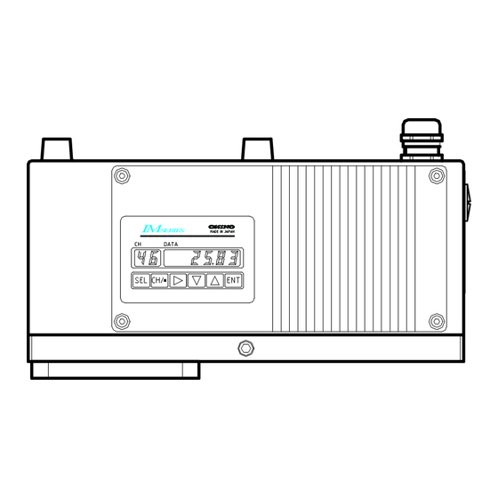
INST.No.INE-477-P1CE Ver.1.00 4.各部の名称と機能 4. Names and Functions 4.1 Names and functions of displays, lamps and keys DATA (4) Setting status (1) Data display lamps (5) Measurement HEAD status lamps HEAD REMOTE (2) Detector unit REAL number display MODE PRESET HOLD (6) Key-lock indicator... -
Page 18: Names And Functions Of
INST.No.INE-477-P1CE Ver.1.00 4.各部の名称と機能 4. Names and Functions 4.1 Names and functions of displays, lamps and keys DATA HEAD HEAD REMOTE REAL MODE HOLD PRESET HEAD HOLD PRESET R / L S / R (7) Function keys MODE IRGMEG2 MADE IN JAPAN Name Function HEAD... -
Page 19: Operation
INST.No.INE-477-P1CE Ver.1.00 5. Operation 5.1 Confirmation before operation Check the following three points before turning on the power. 1) Have the dipswitches been set? (Refer to [3.1 Setting dipswitches].) 2) Are all of connections correct? (Refer to [3.3 Connections]) 3) In the multiple-detector-units connection, have detector unit numbers been set? (Refer to the separate instruction manual for [Infrared multiple-constituents analyzer detector unit IRMA Caution... -
Page 20: Setting Calibration Curves
INST.No.INE-477-P1CE Ver.1.00 5. Operation 5.3 Setting calibration curves Output characteristics of detector units depend upon measuring objects. It may also change according to process conditions or constituent measuring conditions of samples. Accordingly, for accurate measurements, it is required to perform beforehand sample tests of each object and obtain, for moisture measurements, a relationship (This is called as a calibration curve.) between moisture contents (%H O) obtained by a drying method or other measuring methods and... -
Page 21: Calibration Curves
INST.No.INE-477-P1CE Ver.1.00 5. Operation 5.3.1-2) Descriptions of the setting data for calibration curves Setting data name Function (1) Calibration curve An optional number from 1 to 99 can be designated as a calibration curve. Ordinarily it is number designated sequentially from “1”. (2) Computing mode (*) The computing modes selectable differ depending on specifications (number of wavelengths and number of constituents) of a detector unit being connected. -
Page 22: Setting Procedure
INST.No.INE-477-P1CE Ver.1.00 5. Operation 5.3.2 Setting procedure The setting procedures for (1) calibration curve numbers, (2) computing modes and (3) calibration curve coefficients a to a shown in [5.3.1-1) List of the setting data for calibration curves differ depending on specifications (number of wavelengths and number of constituents) of a detector unit being connected. -
Page 23: Being Connected
INST.No.INE-477-P1CE Ver.1.00 5. Operation 5.3.2-2) Setting detector unit numbers and (1) calibration curve numbers ~ (3) calibration curve coefficients for IRMA5000 or 6000 series detector units being connected 1) Use the numeric keys 1 to 9 to set a detector unit HEAD DATA number. -
Page 24: Correcting Calibration Curves
INST.No.INE-477-P1CE Ver.1.00 5. Operation 5.3.2-3) Setting from (4) correction coefficients b to (8) water absorbance 1) Press SEL to enter into the next data setting mode. 2) Set from (4) correction coefficients b to (4) water absorbance with the same key operation as the above [5.3.2.-2]. -
Page 25: Setting Output Limit Values Of
INST.No.INE-477-P1CE Ver.1.00 5. Operation 5.4 Setting output limit values of calibration curves A measured value can be fixed by low limit and high limit absorbance values. When an absorbance becomes less than a low limit absorbance value, a measured value is fixed to YL as shown right. -
Page 26: Procedure For Setting The Data For Output Limit
INST.No.INE-477-P1CE Ver.1.00 5. Operation 5.4.2 Procedure for setting the data for output limit values of calibration curves 5.4.2-1) Setting calibration curve numbers (CH) 1) Use the numeric keys 1 to 9 to set a detector unit number. HEAD 2) Press SEL key and CH key simultaneously for 2 HEAD DATA seconds to display "CH"... -
Page 27: 2-4) Setting A High Limit Absorbance Value (Xh) And A High Limit Measured Value (Yh)
INST.No.INE-477-P1CE Ver.1.00 5. Operation 5.4.2-4) Setting a high limit absorbance value (XH) and a high limit measured value (YH) 1) After the above settings [5.4.2-1)] to 5.4.2-3)], HEAD DATA press SEL key to display “XH" in the CH 1.000 display for entering into the high limit absorbance value XH setting mode. -
Page 28: Selecting Calibration Curve Numbers
INST.No.INE-477-P1CE Ver.1.00 5. Operation 5.5 Selecting calibration curve numbers DATA This is for selecting a calibration curve number whose data for computing moisture contents, thickness or constituent HEAD values have been set in [5.3 Setting calibration curves]. HEAD REMOTE REAL MODE HOLD PRESET... -
Page 29: Setting Operation Conditions I
INST.No.INE-477-P1CE Ver.1.00 5. Operation 5.6 Setting operation conditions I (display/output) This is for setting display/output conditions of a detector unit by this unit. 5.6.1 List of setting data DATA Setting data name Lamp Setting range of data Default value 0.1 to 9.9 (less than 10 sec) HEAD (1) Time constant T lights. -
Page 30: Setting Operation Conditions
INST.No.INE-477-P1CE Ver.1.00 5. Operation 5.7 Setting operation conditions II (MODE setting) For setting various operation conditions of this unit and a detector unit, use the MODE setting. The MODE setting is only available in the absorbance display mode. R e m a r k s For exiting the MODE setting, press SEL key for 2 seconds or the automatic return to the measurement mode is made if no key is pressed for one minute. - Page 31 INST.No.INE-477-P1CE Ver.1.00 5. Operation MODE Setting range Default Setting data name Disp. Remarks Para. of data value 0: Cycle (Circulating display) Displaying a constituent number 1: C1 (Constitute number 1) (For IRMA5000 or 6000 series 0 to 4 2: C2 (Constitute number 2) 5.7.8 detector units only) 3: C3 (Constitute number 3)
-
Page 32: Weight Α, Calibration Constant
INST.No.INE-477-P1CE Ver.1.00 5. Operation 5.7.2 Weight α, calibration constant The weights “α” are values to decide a ratio of 2 wavelengths in 3-wavelength processing. The calibration constants are values obtained in [5.10 Calibration] which have been automatically stored. For setting, press MODE , 6 and then ENT . “1A”... -
Page 33: Sample Temperature Correction Enabled Or
INST.No.INE-477-P1CE Ver.1.00 5. Operation 5.7.5 Sample temperature correction enabled or disabled (This is effective for IRMA1000, 2000, 7000 or 8000 series detector units, or for detector units for 1 constituent in IRMA5000 or 6000 series.) Select the sample temperature correction by a detector unit is enabled or disabled. For setting, press MODE , 1 , 9 and then ENT . -
Page 34: Selecting A Constituent Number For An Analog Output And A Contact Output From A
INST.No.INE-477-P1CE Ver.1.00 5. Operation 5.7.9 Selecting a constituent number for an analog output and a contact output from a detector unit (For detector units for 2 or more constituents in IRMA5000 or 6000 series only) Select a constituent number for an analog output and a contact output from a detector unit. For setting, press MODE , 3 , 1 and then ENT . -
Page 35: Setting Communication Conditions
• Even parity or odd parity: 1 bit • No parity: 2 bits (6) BCC enabled/disabled When CHINO’s private protocol (PriV) is selected, set BCC enabled or disabled. R e m a r k s When MODBUS “rtU” mode protocol is selected, this item will be skipped. -
Page 36: Remote Contact Inputs
INST.No.INE-477-P1CE Ver.1.00 5. Operation 5.8 Remote contact inputs The setting of a calibration curve number, etc. can be executed by using remote contacts. Power Power Protective ground Protective ground 100 -240V AC 24V DC Remote contact inputs Remote contact inputs [IRGMEG2 ] [IRGMEG2 V] (Complying with CE) 5.8.1 Setting detector unit numbers, constituent numbers and... -
Page 37: Calibration (For Performing A Calibration, Read The Paragraph [Calibration] In A Separate Instruction Manual For A Detector Unit Being Connected, Too.)
If the absorbance “x” is not included in range within value of the above table the malfunction of this unit is conceivable. Please contact your nearest agent of CHINO corporation. [Releasing the absorbance display mode setting] 6) After the calibration is completed, press CH , enter a calibration curve number and then press ENT key. -
Page 38: Calibration For Irma5000 Or 6000 Series
If the absorbance “x” is not included in range within value of the above table the malfunction of this unit is conceivable. Please contact your nearest agent of CHINO corporation. [Setting the absorbance display mode] 6) After the calibration is completed, press CH in any computing mode, enter a constituent number and then press ENT . -
Page 39: Creating Calibration Curves
INST.No.INE-477-P1CE Ver.1.00 6. Creating calibration curves Output characteristics of detector units depend upon measuring objects. It may also change according to process conditions or constituent measuring conditions of samples. Accordingly, for accurate measurements, it is required to perform beforehand sample tests of each object and obtain, for moisture measurements, a relationship (This is called as a calibration curve.) between moisture contents (%H O) obtained by a drying method or other measuring methods and... -
Page 40: Inspection And Maintenance
× checker plate. Er01 Nonvolatile memory Writing to or reading from the Return this detector unit to abnormal nonvolatile memory is disabled. CHINO. Er03 Motor rotation The motor stops or rotates Replace the motor. abnormal abnormally. Er06 Computation error Overflow happed in computation Check the output by the output checker plate. -
Page 41: Measures Against Troubles Not Included
(5) By using the output checker plate, check if the data displayed in the absorbance display mode change? (6) When the data remains unchanged, initialize the RAM. If this phenomenon is not still recovered, return this unit to CHINO. 7.3.2 Measured value fluctuates. (1) Is the measuring surface flat? (2) Is the measuring position correct? Make sure that a detector unit does not measure such bottom face as a conveyor belt, etc. -
Page 42: Specifications
INST.No.INE-477-P1CE Ver.1.00 8. Specifications 8.1 Operator interface/display unit IRGMEG2 Model IRGMEG2 IRGMEG2 V (complying with CE) Detector unit input RS-485, Up to 9 sets connectable Analog output 4 to 20mA DC 4 to 20mA DC (Load resistance: 500Ω or less) 2 outputs (Load resistance: 500Ω... - Page 43 32-8, KUMANO-CHO, ITABASHI-KU, TOKYO 173-8632 Telephone: +81-3-3956-2171 Facsimile: +81-3-3956-0915 Web site http://www.chino.co.jp/ INE-477-P1CE Nov-'04 IM series infrared multiple-constituents analyzer Operator interface/display unit Model IRGMEG2 Printed in Japan...
Need help?
Do you have a question about the IM Series and is the answer not in the manual?
Questions and answers