Table of Contents
Advertisement
Quick Links
This 'original instructions' document assumes that the operator carrying out any operation with this
product is trained and competent to do so. This manual does not attempt to cover all details or variations
in the equipment. Nor does this manual claim to provide for every possible contingency met in connection
with the installation, operation, or maintenance thereof. Should further information be desired, or should
a particular problem arise which is not covered in sufficient detail, the matter should be referred to
Hi-Force.
OPERATING INSTRUCTION MANUAL
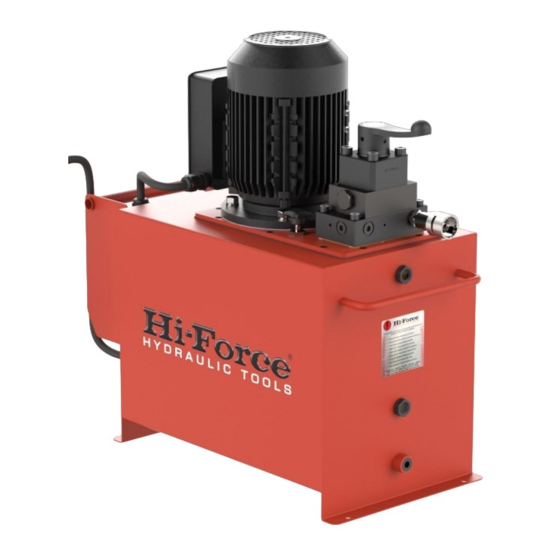
HEP4 & HEP5 SERIES | ELECTRIC DRIVEN PUMPS
• HEP4 - GENERAL DUTY, HIGH FLOW
• HEP5 - GENERAL DUTY, ULTRA-HIGH FLOW
Hi-Force HEP4 and HEP5 series Electric Driven Hydraulic Pumps are designed to operate high pressure
hydraulic cylinders and tools with a maximum working pressure of 700Bar. This manual applies to the Hi-
Force HEP4 and HEP5 series, Electric Driven Hydraulic Pumps. It contains the latest product information
available at the time of publication and approval. Hi-Force reserves the right to make changes to this
document at any time without notice.
Operating Instruction Manual:
OM-HEP4/5-01
1
From Serial Number:
BN0101
Advertisement
Table of Contents

Subscribe to Our Youtube Channel
Related Manuals for Hi-Force HEP4 Series


Summary of Contents for Hi-Force HEP4 Series
- Page 1 700Bar. This manual applies to the Hi- Force HEP4 and HEP5 series, Electric Driven Hydraulic Pumps. It contains the latest product information available at the time of publication and approval. Hi-Force reserves the right to make changes to this document at any time without notice.
-
Page 2: Table Of Contents
Operating Instruction Manual: From Serial Number: OM-HEP4/5-01 BN0101 Table of Contents 1.0 Inspection upon Receipt ..................3 2.0 Safety Precautions ....................3 2.1 Introduction ......................3 2.2 Work Area Safety ....................3 2.3 General Hydraulic System Safety Precautions ..........3 2.4 Hydraulic Pump Specific Safety Precautions ........... -
Page 3: Inspection Upon Receipt
If in doubt on the correct use of any Hi-Force equipment, contact your nearest Hi-Force office or distributor. Only qualified personnel should be allowed to operate hydraulic equipment. If an operator has not been trained on high-pressure hydraulic equipment and its safe usage, consult your local Hi-Force sales office or distributor who can offer training courses for operators. - Page 4 • Immediately replace any worn or damaged parts using genuine Hi-Force parts only. • DO NOT remove any labels from the product. Replace any damaged or unreadable label immediately.
-
Page 5: Hydraulic Pump Specific Safety Precautions
3.0 Declaration of Incorporation / Conformity Hi-Force declares that this product has been tested and complies with the standards set out in the relevant EU directives. The EU Declaration of Incorporation / Conformity is included as Annex A to this instruction... -
Page 6: Component Identification
Operating Instruction Manual: From Serial Number: OM-HEP4/5-01 BN0101 4.0 Component Identification Hydraulic Oil Drain Plug Oil Filler Breather Cap Hydraulic Oil Level Gauge Motor *** Hydraulic Service Connections * On/Off Switches Directional Control Valve ** Adjustable Pressure Relief Valve Oil Reservoir Modular Electric Tray * One or two ports, depending on valve type. - Page 7 Operating Instruction Manual: From Serial Number: OM-HEP4/5-01 BN0101 Figure 4.2: Component Identification...
-
Page 8: Installation/Setup
Operating Instruction Manual: From Serial Number: OM-HEP4/5-01 BN0101 5.0 Installation/Setup 5.1 Before First Use 1. Immediately after unpacking, examine the pump for signs of transit damage and if found contact the shipping company. 2. Remove the temporary transit fitting / plate which is fitted in the position of the oil filler breather cap (8) and fit the oil filler breather cap which is packed separately. -
Page 9: Filling The Pump With Oil
Once satisfied the supply is suitable, an electrical connection can be made. NOTE: Supply voltages vary from country to country. Hi-Force pumps will operate within the normal voltage tolerance ranges, but in extreme cases where they are operated for long periods at high pressures and in low voltage conditions, the motor may overheat and shut down. -
Page 10: Hydraulic Connections
NOTE: When longer hoses are used (especially in the case of smaller capacity Figure 5.2 cylinders), the above procedure may not remove all the air from the system. In these cases, contact your Hi-Force representative for advice on pre-filling hoses with hydraulic oil. -
Page 11: Operation
BN0101 6.0 Operation Hi-Force will not always be aware of what equipment this pump will be used to power. It is the responsibility of the owner and all operators to read, understand and comply with all appropriate safety warnings and operating instructions relating to the equipment being used. -
Page 12: Pumps With Manual Valves
Operating Instruction Manual: From Serial Number: OM-HEP4/5-01 BN0101 6.2 Pumps with Manual Valves 1. Set the adjustable pressure relief valve (5) if required. See section 6.1 for details. 2. With all hydraulic connections and an electrical connection made turn the motor on by pressing the green ‘ON’... -
Page 13: Pumps With Solenoid Valves
Inspect the pump for damage after each use. • Change the oil every 500 working hours using high quality ISO46 hydraulic oil. • Zero the pump pressure before storing. • Have the pump serviced regularly by a Hi-Force authorised repair centre. -
Page 14: Specifications
Operating Instruction Manual: From Serial Number: OM-HEP4/5-01 BN0101 8.0 Specifications An average A-Weighted sound pressure level of 75dB was measured for undefined workspaces, as per EU Directive 2006/42/EC Section 1.7.4.2 (u). 8.1 HEP4 Specifications Refer to the nameplate on the pump for model identification. HEP4 │... -
Page 15: Hep4 Electrical Pump Characteristics
Operating Instruction Manual: From Serial Number: OM-HEP4/5-01 BN0101 8.2 HEP4 Electrical pump Characteristics Refer to the nameplate on the pump for model identification. Motor Motor Motor Motor Voltage Frequency Current Output 110V-1Ph 50 Hz 16 A 1.1 kW 9.3 – 9.5 A 230V-1Ph 50 Hz 1.5 kW... -
Page 16: System Components / Accessories
Operating Instruction Manual: From Serial Number: OM-HEP4/5-01 BN0101 10.0 System Components / Accessories (Refer to the Hi-force website or latest Hi-Force catalogue, Section: System Components for further details) • High Pressure Hydraulic Hoses • Manifolds and Manifold Assemblies • Flow Control Valve •... -
Page 17: Troubleshooting
From Serial Number: OM-HEP4/5-01 BN0101 11.0 Troubleshooting Hi-Force HEP4 & HEP5 electric driven hydraulic pumps should be serviced and repaired only by authorised Hi-Force repair centres. The following table gives possible causes and solutions for common problems. TROUBLESHOOTING GUIDE Problem... - Page 18 Check for correct system setup. Check functioning correctly. to pump. couplers (if fitted) for full engagement b. Pump solenoid faulty. Contact your local Hi-Force office/distributor. See cylinder/tool’s troubleshooting guide or c. Cylinder/tool fault. contact your local Hi-Force office/distributor. d. Low oil level Add oil as per section 5.2.
- Page 19 Operating Instruction Manual: From Serial Number: OM-HEP4/5-01 BN0101 Head Office: Hi-Force Limited Prospect Way, Daventry Northamptonshire NN11 8PL United Kingdom Tel: + 44 1327 301000 | Fax: + 44 1327 706555 www.hi-force.com Regional Offices: For information on our offices worldwide, scan the below QR code...
Need help?
Do you have a question about the HEP4 Series and is the answer not in the manual?
Questions and answers