Table of Contents
Advertisement
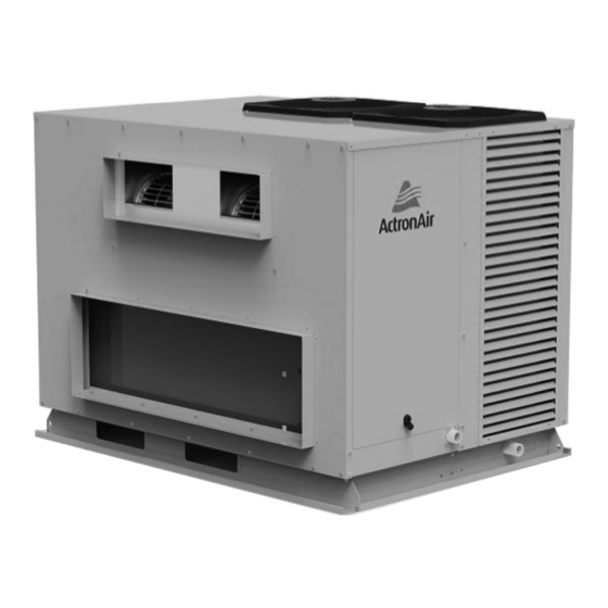
Variable Capacity Commercial (R-32 Series)
Inverter Package Ducted Units
Installation and Commissioning Guide
Model Numbers
PRV15AT-TFFT-EV*
PRV17AT-TFFT-EV*
PRV15AT-TVFT-EV
PRV17AT-TVFT-EV
Under/Over Unit
*
Front discharge Air Handling Option shown
for illustration purposes only.
IMPORTANT NOTE:
Please read this manual carefully before installing or operating your air conditioning unit.
Advertisement
Table of Contents

Related Manuals for ActronAir PRV15AT-TFFT-EV Series


Summary of Contents for ActronAir PRV15AT-TFFT-EV Series
- Page 1 Variable Capacity Commercial (R-32 Series) Inverter Package Ducted Units Installation and Commissioning Guide Model Numbers PRV15AT-TFFT-EV* PRV17AT-TFFT-EV* PRV15AT-TVFT-EV PRV17AT-TVFT-EV Under/Over Unit Front discharge Air Handling Option shown for illustration purposes only. IMPORTANT NOTE: Please read this manual carefully before installing or operating your air conditioning unit.
-
Page 2: Table Of Contents
Variable Capacity Package R-32 Installation and Commissioning Guide Table of Contents Introduction ������������������������������������������������������������������������������������������������������������������������������������4 General Information ������������������������������������������������������������������������������������������������������������������������5 Safety Instructions ��������������������������������������������������������������������������������������������������������������������������7 Installation Information �������������������������������������������������������������������������������������������������������������������8 Operation Manual Access ����������������������������������������������������������������������������������������������������������������9 Wall Controller Options ����������������������������������������������������������������������������������������������������������������� 10 Wall Controller Options Wiring Configuration : Recommended Wiring Configuration : Alternate Components Overview ������������������������������������������������������������������������������������������������������������������... - Page 3 Variable Capacity Package R-32 Installation and Commissioning Guide Table of Contents Configuring and Commissioning Setup ������������������������������������������������������������������������������������������ 29 Menu and Navigation Configuring Compressor and Capacity(cnFg) Configuring Control Source (CtrS) Demand Response Management ���������������������������������������������������������������������������������������������������� 31 Third Party Control Input (Indoor and/or Outdoor Board) �������������������������������������������������������������� 32 0-10V Analogue Input for Compressor and Indoor Fan 0-10V Analogue Input for Compressor with Fixed Indoor Fan Speed Input for Fixed Compressor with Fixed Indoor Fan Speed...
-
Page 4: Introduction
Check your air conditioning unit and all items against the invoice upon receiving your shipment. Inspect the unit, components and accessories for any sign of damage. If there is any damage to the unit, contact ActronAir Customer Care Department immediately on: 1300 522 722 to obtain a Goods Return Number. -
Page 5: General Information
For optimum efficiency, your air conditioning unit will deliver just the right amount of cooling or heating capacity. Energy Efficient Refrigeration Circuits The ActronAir system is designed with a highly efficient refrigeration circuit that delivers only the amount of cooling or heating actually required to maintain your desired comfort at the most optimum efficiency. - Page 6 The air conditioning system is supplied with zero ozone depleting refrigerant, which has no phase out or replacement concern. With cooling and heating performance capacity that are among the best in the market, the ActronAir air conditioning units provide the solution for the reduction of energy consumption, CO2 emission, high fuel dependency and high network grid demand.
-
Page 7: Safety Instructions
Variable Capacity Package R-32 Installation and Commissioning Guide Safety Instructions • Only licensed HVAC technicians* should install and service air conditioning equipment. Improper service or alteration by an unqualifi ed technician could result in signifi cant and major damage to the product or property which may render your warranty null and void. -
Page 8: Installation Information
Variable Capacity Package R-32 Installation and Commissioning Guide Installation Information All service technicians handling refrigerant must be licensed to handle refrigerant gases. Recover and Recycle Refrigerants Never release refrigerant to the atmosphere! It is an offence in Australia to do so. Always recover, recycle and reuse refrigerants. -
Page 9: Operation Manual Access
CAUTION This outdoor unit is designed to match only with an ActronAir indoor unit as specified in the Technical Selection Catalogue. The unit is supplied with factory charged refrigerant as stated in the Rating Label. The use other material as a refrigerant may cause explosion and/or personal injury. -
Page 10: Wall Controller Options
Variable Capacity Package R-32 Installation and Commissioning Guide Wall Controller Options Wall Controller Options A maximum of three (3) wall controllers in the below combinations is allowed per unit. See below table. Wall Controllers Options 1st Option 2nd Option 3rd Option LR7-1 / LC7-2 4th Option LR7-1 / LC7-2... -
Page 11: Wiring Configuration : Recommended
Variable Capacity Package R-32 Installation and Commissioning Guide Wiring Confi guration : Recommended NOTES • Diagram shown below is a general representation only. Refer to individual unit wiring diagram for complete wiring connection details. • Long runs beside Mains cables or TV antenna cables should be avoided. •... -
Page 12: Wiring Configuration : Alternate
Variable Capacity Package R-32 Installation and Commissioning Guide Wiring Confi guration : Alternate NOTES • Diagram shown below is a general representation only. Refer to individual unit wiring diagram for complete wiring connection details. • Long runs beside Mains cables or TV antenna cables should be avoided. •... -
Page 13: Components Overview
Variable Capacity Package R-32 Installation and Commissioning Guide Components Overview EVAP REAR ACCESS TOP PANEL FAN- TWIN DECK FAN- TWIN DECK ELECTRICAL CONTROL PANEL* OUTDOOR AXIAL FANS EVAPORATOR EVAPORATOR COIL ASSY. ASSEMBLY EVAP FRONT EVAP FRONT GRILLE PANEL ACCESS CONDENSER ACCUMULATOR COIL ASSY. -
Page 14: Control Panel
Variable Capacity Package R-32 Installation and Commissioning Guide Control Panel VSD (BACK) VSD (FRONT) ELECTRICAL CONTROL PANEL Installation and Commissioning Guide - Package Ducted Variable Capacity (R-32) Doc. No.0525-106 Ver. 1 221012... -
Page 15: Electrical Control Panel
Variable Capacity Package R-32 Installation and Commissioning Guide Electrical Control Panel OUTDOOR CONTROL BOARD INDOOR CONTROL BOARD (CMI) CMI POWER SUPPLY OUTDOOR MAIN TERMINAL BLOCK VSD CIRCUIT BREAKER CONTROL BOARD CIRCUIT BREAKER Installation and Commissioning Guide - Package Ducted Variable Capacity (R-32) Doc. -
Page 16: Compressor Variable Speed Drive (Vsd) Assembly - Front
Variable Capacity Package R-32 Installation and Commissioning Guide Compressor Variable Speed Drive (VSD) Assembly - Front EMI FILTER BOARD DC CAPACITOR BOARD COMPRESSOR VSD Compressor Variable Speed Drive (VSD) Assembly - Back CHOKE INDUCTOR HEAT SINK COVER COMPRESSOR VSD - HEAT SINK Installation and Commissioning Guide - Package Ducted Variable Capacity (R-32) Doc. -
Page 17: Unit Dimensions, Clearances And Weights
TO ENSURE ALL CONDENSATION IS 1136 O/A REMOVED EFFICIENTLY TO AVOID WATER POOLING WITHIN THE CONDENSER. IF A SINGLE CONDENSATION DRAIN POINT IS REQUIRED, ACTRONAIR RECOMMENDS THE INSTALLATION OF A CONDENSER TRAY. DRAWING IS SUBJECT TO CHANGE WITHOUT NOTICE 1100... -
Page 18: Service Clearances, Airflow Allowances And Weights
1000 mm between the units or between the unit and the outside perimeter is available. 3. Minimum service access areas and spaces for airflow clearances are responsibilities of the installer, ActronAir will not be held liable for any extra charges incurred due to lack of access and space for airflow. -
Page 19: Unit Lifting Procedure
Variable Capacity Package R-32 Installation and Commissioning Guide Unit Lifting Procedure WARNING WH&S regulations must be observed and will take precedence during lifting process. NOTE All drawings are for illustration purposes only. Actual unit may vary depending on the model. Crane Lifting Method Crane lifting method is recommended for high rise lifting. - Page 20 Variable Capacity Package R-32 Installation and Commissioning Guide 4. SPREADER BARS must be used when lifting the unit. Ensure that the spreader bar is slightly larger than the base. 5. Test lift the unit to determine exact unit balance and stability before hoisting it to the installation location. Fork Lift Method DANGER Make sure rigging equipment, accessories and plant are suffi ciently and safely capable to lift the unit in order to prevent...
-
Page 21: Outdoor Unit Preparation
Variable Capacity Package R-32 Installation and Commissioning Guide Outdoor Unit Preparation WARNING Live electrical within enclosure. Isolate electrical supply before removing panels. Authorised technicians access only. 1. Rotate the Hex Recess 90 degrees using 8mm allen key and remove the Access Panel-Electrical as illustrated below. ACCESS Removal Order: Rotate the Hex Recess... -
Page 22: Safety Drain Tray
Variable Capacity Package R-32 Installation and Commissioning Guide Safety Drain Tray NOTES • Do not use pipes or tube coming out from the unit to lift the unit. • Support drain line for long pipe run. • Refer to unit dimension page for specifi cation of drain connectors. •... -
Page 23: Electrical Installation
Variable Capacity Package R-32 Installation and Commissioning Guide Electrical Installation All electrical work must be carried out by a qualified technician. Make sure all wiring is in accordance with local wiring rules. Wiring connections should be made in accordance with the wiring diagram provided. DANGER Live Electrical Supply ! •... -
Page 24: Wiring Diagram
Variable Capacity Package R-32 Installation and Commissioning Guide Wiring Diagram Installation and Commissioning Guide - Package Ducted Variable Capacity (R-32) Doc. No.0525-106 Ver. 1 221012... -
Page 25: Electrical Connection
Variable Capacity Package R-32 Installation and Commissioning Guide Electrical Connection NOTES • To minimise noise interference, Data and Power cable clearance should be maintained as much as possible. • All drawings are for illustration purposes only. Actual unit may vary depending on the model. DETAILED WIRING DIAGRAM IS PROVIDED WITH THE UNIT�... -
Page 26: Circuit Breaker Size And Cable Size Recommendation
Variable Capacity Package R-32 Installation and Commissioning Guide Circuit Breaker Size and Cable Size Recommendation Circuit Breaker Size Cable Size (mm²) Amps MAIN O�D� to I�D� Model CRV13AS / EVV13AS / EFV13AS 32.0 CRV15AS / EVV15AS / EFV15AS 40.0 10.0 CRV17AS / EVV17AS / EFV17AS CRV13AT / EVV13AS / EFV13AS 16.0... -
Page 27: Wiring Connections
Variable Capacity Package R-32 Installation and Commissioning Guide Wiring Connections LR7-1 and LC7-2 Wall Control Wiring Connections INDOOR WALL CONTROL WIRING CONTROL BOARD POWER: - BROWN / ORANGE 485 A: - BLUE WALL CONTROLLER +12V A 485 B: - BLUE-WHITE GND: - BROWN-WHITE / ORANGE-WHITE NOT USED: - GREEN / GREEN-WHITE... -
Page 28: Lm-Rs-2 Optional Sensor Wiring Connections
Variable Capacity Package R-32 Installation and Commissioning Guide LM-RS-2 Optional Sensor Wiring Connections INDOOR CONTROL REMOTE SENSOR WIRING BOARD PAIR 1: - BLUE / BLUE-WHITE PAIR 2: - ORANGE / ORANGE-WHITE TEMP PAIR 3: - GREEN / GREEN-WHITE SENSORS PAIR 4: - BROWN / BROWN-WHITE OPTIONAL OPTIONAL OPTIONAL... -
Page 29: Configuring And Commissioning Setup
Variable Capacity Package R-32 Installation and Commissioning Guide Configuring and Commissioning Setup Menu and Navigation CCS = Cooling compressor speed Display system's status and settings (Settings) (Display) HCS = Heating compressor speed CCT = Cooling mode critical temp. Service use only condition. -
Page 30: Configuring Compressor And Capacity(Cnfg)
Configurable settings are as follows: Third Party Control The unit can be controlled by non-ActronAir wall control. To do this, CtrS on the Outdoor Board has to be set to Ct� 0. For connection details, see the wiring diagram supplied with the outdoor unit. -
Page 31: Demand Response Management
Variable Capacity Package R-32 Installation and Commissioning Guide Demand Response Management These products are compliant to AS/NZS 4577.3.1:2012 Refer to Control Panel section for the location of the Control CRA13-15-17AS-A Board (ODU CPU Board) ODU CPU COMPONENT OV BOARD ADVANCE +12V/COM DRM 3/COMP DRM 2/FAN... -
Page 32: Third Party Control Input (Indoor And/Or Outdoor Board)
Variable Capacity Package R-32 Installation and Commissioning Guide Third Party Control Input (Indoor and/or Outdoor Board) This option allows Fan, Compressor and Reversing Valve to be controlled by a Third Party Control. There are two ways on how the Indoor Fan may be controlled, using 0-10V Analogue Input or Fixed Indoor Fan Speed. NOTE •... -
Page 33: 0-10V Analogue Input For Compressor With Fixed Indoor Fan Speed
Variable Capacity Package R-32 Installation and Commissioning Guide Input (DC) Output Compressor Status 0 - 0.99 V 1 - 1.49 V 0 or 20% Off/On (hysteresis) 1.5 - 9.5 V 20% to 100% 9.5 - 10 V 100% NOTES • As the compressor turns ON and the Indoor fan signal is not available then indoor fan will start to run on medium PWM speed. -
Page 34: Input For Fixed Compressor With Fixed Indoor Fan Speed
Variable Capacity Package R-32 Installation and Commissioning Guide Input for Fixed Compressor with Fixed Indoor Fan Speed This feature allows for both Compressor and Indoor Fan to be controlled externally (ON/OFF only). Indoor Fan Setting (Indoor Board) InZone Board CMI Board No additional setting required. -
Page 35: Run And Fault Indication Output (Outdoor Board)
Variable Capacity Package R-32 Installation and Commissioning Guide Input (DC) Output Fan Status 0.0 V to 0.99 V 1.0 V to 1.49 V 0 or 20% Off or On 1.5 V to 9.5 V 20% to 100% 9.5 V to 10 V 100% Fan, Compressor and Reversing Valve Connection (Outdoor Board) +12V... -
Page 36: Remote On/Off
Variable Capacity Package R-32 Installation and Commissioning Guide Fault Indication ODU CPU OUTPUT BOARD INDICATORS NC OUTPUT VOLTAGE INPUT NO OUTPUT To indicate any system fault, outdoor controller will provide a signal through the Fault Indication relay. An installer can use either NC or NO output as per their requirements. -
Page 37: Indoor Fan Commissioning
Variable Capacity Package R-32 Installation and Commissioning Guide Indoor Fan Commissioning PRV15AT FAN DATA* EXTERNAL STATIC PRESSURE (Pa) AIRFLOW (l/s) % PWM % PWM % PWM % PWM % PWM MOTOR / BLOWER LIMIT REDUCED AIRFLOW** (COMPRESSOR OFF) EXTERNAL STATIC PRESSURE (Pa) AIRFLOW (l/s) % PWM... - Page 38 Variable Capacity Package R-32 Installation and Commissioning Guide EVA15AS / EFV15AS : Third Party Application Fan Curve Installation and Commissioning Guide - Package Ducted Variable Capacity (R-32) Doc. No.0525-106 Ver. 1 221012...
-
Page 39: Prv17At
Variable Capacity Package R-32 Installation and Commissioning Guide PRV17AT FAN DATA* EXTERNAL STATIC PRESSURE (Pa) AIRFLOW (l/s) % PWM % PWM % PWM % PWM % PWM MOTOR / BLOWER LIMIT 1000 1025 1050 1060 REDUCED AIRFLOW** (COMPRESSOR OFF) EXTERNAL STATIC PRESSURE (Pa) AIRFLOW (l/s) % PWM... - Page 40 Variable Capacity Package R-32 Installation and Commissioning Guide PRV17AT : Third Party Application Fan Curve Installation and Commissioning Guide - Package Ducted Variable Capacity (R-32) Doc. No.0525-106 Ver. 1 221012...
-
Page 41: Refrigerant Charging
Variable Capacity Package R-32 Installation and Commissioning Guide Refrigerant Charging • The unit is supplied with factory charged refrigerant as stated in the Rating Label. The use other material as a refrigerant may cause explosion and/or personal injury. • Be aware of all the relevant regulations concerning the handling of refrigerant. •... -
Page 42: Charging Method: Subcooling And Superheat
Variable Capacity Package R-32 Installation and Commissioning Guide Charging Method: Subcooling and Superheat Parameters: LLT = Liquid Line Temperature SLT = Suction Line Temperature SCT = Saturated Condensing Temperature SST = Saturated Suction Temperature Cooling and Heating Operation: Adjust the refrigerant charge to obtain the correct super heat and sub-cool for optimal performance as follows: 1. -
Page 43: Recording Of Final R-32 Refrigerant Charge
Variable Capacity Package R-32 Installation and Commissioning Guide 3. If superheat is within the range (see charging table), there is no need to add/remove refrigerant. • If superheat is lower than minimum, it means that liquid refrigerant may be returning to compressor. It is necessary to remove refrigerant or check EEV settings. - Page 44 Variable Capacity Package R-32 Installation and Commissioning Guide CHARGING TABLE Temp Pressure Temp Pressure Temp Pressure Temp Pressure °C °C °C °C 1040 2439 1073 2500 1108 2564 1143 2628 1180 2694 1217 2760 1255 2829 1293 2898 1333 2969 1373 3040 1415...
-
Page 45: Maintenance
Variable Capacity Package R-32 Installation and Commissioning Guide Maintenance Maintenance Procedures This section describes the procedures that must be performed as a part of normal maintenance program. Regular servicing of equipment by licensed technician is highly recommended. Regular servicing of your unit helps in maintaining its optimum performance and reliability. - Page 46 Variable Capacity Package R-32 Installation and Commissioning Guide WARNING Do Not Use High Alkaline Detergent! When using detergent for coil cleaning, ensure that the alkaline level is no higher than 8.5, which can cause corrosion damage to the coils. DANGER No Water into the Electrical Compartments! Ensure consideration is given to the possibility of water entering the electrical compartments during cleaning of the condenser coil.
-
Page 47: Maintenance Frequency Checklist
Variable Capacity Package R-32 Installation and Commissioning Guide Maintenance Frequency Checklist Regular servicing of equipment by a qualified technician is recommended every 12 months for residential applications and every quarter for commercial applications. Regular servicing of your unit helps in maintaining its optimum performance and reliability. - Page 48 Variable Capacity Package R-32 Installation and Commissioning Guide OUTDOOR UNIT Service Period Parts Detail of Service Check Service Methods For highly corrosive environment, wash panels Casing / Panels Visual check for damage, rust quarterly with water and neutral and Frames and dust accumulation.
-
Page 49: Version History
Variable Capacity Package R-32 Installation and Commissioning Guide Version History DOCUMENT VERSION BOM VERSION UPDATE HISTORY Ver 1 -0100 Released Installation and Commissioning Guide - Package Ducted Variable Capacity (R-32) Doc. No.0525-106 Ver. 1 221012... - Page 50 ©Copyright 2022 Actron Engineering Pty Limited ABN 34 002767240. ®Registered Trade Marks of Actron Engineering Pty Limited. ActronAir is constantly seeking ways to improve the design of its products. Therefore, specifi cations are subject to change without notice. Document: 0525-106 Ver. 1 Issue Date: 10/2022...
Need help?
Do you have a question about the PRV15AT-TFFT-EV Series and is the answer not in the manual?
Questions and answers