Table of Contents
Advertisement
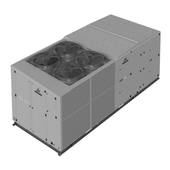
Hercules
Package Unit
Installation and Commissioning Guide
HERCULES SERIES
PKV1400T
PKV2000T
IMPORTANT NOTE:
IMPORTANT NOTE:
Please read this manual carefully before installing or operating your air conditioning unit.
Please read this manual carefully before installing or operating your air conditioning unit.
Advertisement
Table of Contents

Related Manuals for ActronAir HERCULES Series


Summary of Contents for ActronAir HERCULES Series
- Page 1 Hercules Package Unit Installation and Commissioning Guide HERCULES SERIES PKV1400T PKV2000T IMPORTANT NOTE: IMPORTANT NOTE: Please read this manual carefully before installing or operating your air conditioning unit. Please read this manual carefully before installing or operating your air conditioning unit.
-
Page 2: Table Of Contents
Hercules Package Unit Installation and Commissioning Guide Table of Contents . Introduction ........................... . Safety Precautions .......................... . General Information ........................Installation Information ........................Components Overview ........................Electrical Panel Overview ......................Unit Dimensions ..........................Unit Lifting Procedures ........................ - Page 3 Hercules Package Unit Installation and Commissioning Guide . Unit Control Mode ........................Internal Sensors with Optional Basic BMS . External Inputs . BMS Demand (Advanced BMS) . Indoor Fans, Outdoor Fans and Compressors Addresses .............. . Sensors Detail ..........................
- Page 4 Check your air conditioning unit and all items against the invoice upon receiving your shipment. Inspect the unit, components and accessories for any sign of damage. If there is any damage to the unit, contact ActronAir Customer Care Department immediately on: 1300 522 722 to obtain a Goods Return Number.
-
Page 5: Safety Precautions
The customer, both end user/specifier and installer, assume all liability and risks relating to the configuration of the product in order to reach the expected results in relation to the specific design and system installation. ActronAir, based on specific agreements, may be consulted for the positive commissioning, installation and application of the unit, however in no case does it accept liability for the correct operation of the final equipment. - Page 6 Hercules Package Unit Installation and Commissioning Guide DANGER Hazardous Voltage - Risk of Electrocution. TURN-OFF the power from main isolator before proceeding with any service work of the unit. Observe proper LOCK-OUT/TAG- OUT (LOTO) procedures for electrical appliances in order to prevent accidental switching-on of the power supply. Extreme care and caution must be observed should there be a need to work on live circuit.
- Page 7 Hercules Package Unit Installation and Commissioning Guide ACCESS DOOR RETURN AIR (Negative Pressure Side) ACCESS DOOR SUPPLY AIR (Positive Pressure Side) ID PLUG FANS X 4 WING NUT CABLE - Limiting Door Opening (Safety Cable) EVAPORATOR SECTION NOTES As an added safety feature, a door opening limiting cable (safety cable) is provided which is locked to the Supply Air Baffles and bolted with a Wing Nut into the inside of the supply air door.
-
Page 8: General Information
Energy Efficient Refrigeration Circuits The ActronAir Hercules refrigeration system was designed with the application of two separate variable capacity circuits that deliver only the required amount of cooling or heating to maintain your desired space comfort at optimum efficiency. -
Page 9: Installation Information
04. Installation Information Refrigerant Handling and Accountability ActronAir strongly urges that all service technicians make every eff ort to eliminate and/or vigorously reduce the emission of refrigerants to the atmosphere. Everyone must act in a responsible manner to conserve refrigerants. - Page 10 Hercules Package Unit Installation and Commissioning Guide INSTALLATION PREPARATION (Pre-Installation considerations) The following items must be considered before beginning the unit installation: • Verify the unit capacities and ratings with the unit nameplate. • The unit must be installed in accordance with relevant authority regulations. •...
- Page 11 Hercules Package Unit Installation and Commissioning Guide Nomenclatures UNIT OPTIONS and ACCESSORIES P K V 2 0 0 0 T - D E L T - V V - E K L W - 0 4 V 3 2 1 AIR HANDING VARIATION TYPE REVISION...
- Page 12 Hercules Package Unit Installation and Commissioning Guide Hercules Airflow Low Options RIGHT HAND LEFT SIDE VERTICAL END RETURN RETURN TOP SUPPLY RETURN LEFT HAND SIDE SUPPLY RIGHT HAND VERTICAL END RETURN RIGHT SIDE RETURN RIGHT HAND SIDE SUPPLY BOTTOM RETURN DOWN SUPPLY NOTES 1.
- Page 13 Hercules Package Unit Installation and Commissioning Guide “E” Economy Cycle Without Spill Air OUTSIDE AIR DAMPER RETURN AIR DAMPER NOTES 1. For units with Optional Economy Cycle, Return Air Sensor needs to be fitted by the installer specific to site requirements.
-
Page 14: Components Overview
Hercules Package Unit Installation and Commissioning Guide 05. Components Overview Installation and Commissioning Guide - Hercules Package Unit Doc. No.0525-021 Ver. 21 221110... -
Page 15: Electrical Panel Overview
Hercules Package Unit Installation and Commissioning Guide 06.Electrical Panel Overview TRANSFORMER MSCB * 240VAC TERMINAL MSCB * INDOOR FANS 24VAC BLOCKS COMPRESSOR # 1 CONTACTORS RCBO CONTROL CRANKCASE ISOLATOR HEATER 230V GPO CONTROL INTERFACE VARIABLE VARIABLE MSCB * MSCB * TERMINAL COMPRESSOR COMPRESSOR... -
Page 16: Unit Dimensions
Hercules Package Unit Installation and Commissioning Guide 07. Unit Dimensions Installation and Commissioning Guide - Hercules Package Unit Doc. No.0525-021 Ver. 21 221110... - Page 17 Hercules Package Unit Installation and Commissioning Guide Service Access Areas and Airfl ow Clearances 1500 mm (SMALL CLEARANCE) * AIRFLOW AND SERVICE CLEARANCE FOR LH OUTDOOR COIL OUTDOOR FANS INDOOR FAN OUTDOOR COIL 500 MM SERVICE CLEARANCE 1200 mm IF NO RETURN AIR DUCT SERVICE CONNECTED COMP...
- Page 18 1. All dimensions are in mm unless specified. Do not scale drawing. 2. Refer to corresponding unit dimensional drawing for mounting hole details. 3. Drawings are available on ActronAir website, please contact ActronAir Technical Support for further information on 1800 119 229.
-
Page 19: Unit Lifting Procedures
Hercules Package Unit Installation and Commissioning Guide 08. Unit Lifting Procedures 08.01. Crane Lifting Method WARNING WH&S regulations must be observed and will take precedence during lifting process. NOTE Crane lifting is recommended over forklift method. Connect the loop ends of slings into shackle Provide rubber pads to prevent damage... -
Page 20: Forklift Method
Hercules Package Unit Installation and Commissioning Guide 08.02. Forklift Method PACKAGE UNIT 1320 UNIT FORK LIFTING HOLE DIMENSIONS (All dimensions in mm). COMPRESSOR CAUTION DO NOT LIFT UNIT at this end. Procedure: 1. To move the unit around with a forklift, insert the fork tines through the pallet, as shown. 2. -
Page 21: Condensate And Safety Tray Drainage Instructions
Hercules Package Unit Installation and Commissioning Guide 09. Condensate and Safety Tray Drainage Instructions Suggested Minimum Slope To Ensure Correct Drainage OUTDOOR COIL COMP Condensate Drain Coupling Ø 31.8 mm (1-1/4”) COMP BSP Female Thread (1 x each side) OUTDOOR COIL Ensure Drain Pipes slope down at a Condensate Drain... -
Page 22: Banking Of Units
Hercules Package Unit Installation and Commissioning Guide 10. Banking of Units Standard Units Without The Optional Outside Air and Spill Air **** CONFIGURATION 1 1500 mm (SMALL CLEARANCE) AIRFLOW AND SERVICE CLEARANCE LH OUTDOOR COIL OUTDOOR FANS INDOOR FAN OUTDOOR COIL OUTDOOR COIL OUTDOOR COIL UNIT 1... -
Page 23: Unit Preparation
Hercules Package Unit Installation and Commissioning Guide * Airflow clearance of 1200 mm is for open air space installation, a minimum of 2500 mm airflow clearance must be provided for close space areas with walls higher than the unit. Please note that under all circumstances, condenser air must not recirculate back onto condenser coil. - Page 24 Hercules Package Unit Installation and Commissioning Guide Attach the Supply Air and Return Air Angles to their respective opening by following Detail A procedure below: Fig.3 Supply Air and Return Air Angles Installation IMPORTANT NOTES Down Supply / Bottom Return angles are not factory fi tted. These are to be fi...
- Page 25 Hercules Package Unit Installation and Commissioning Guide 3. Install Air Filters 4. Replace Access Panel - Air Filter • Install Air Filters (16 pcs. required) by sliding the fi lters • Follow Steps 1-2 above in order to replace Access Panel - one at a time in the provided Filter Rails.
-
Page 26: Electrical Power Supply Connection
Hercules Package Unit Installation and Commissioning Guide 12. Electrical Power Supply Connection DANGER Hazardous Voltage ! • During installation of your air conditioning unit, it may be necessary to work in close proximity to live electricity. Always make sure that all power supply, including remote controls, are disconnected before performing installation and commissioning tasks. -
Page 27: Maximum Cable Lengths
13. Maximum Cable Lengths ROOM AIR TEMPERATURE SENSORS (OPTIONAL REMOTE RE-LOCATION) (OPTIONAL DUAL CONTROL) CONTROL INTERFACE ** CONTROL INTERFACE ActronAir CP10 ActronAir CP05 / CP10 (Factory Supplied) ActronAir 2060-030 * (Purchased Separately) ActronAir LM-RS (Factory Supplied) (Optional) NTC SENSOR CABLE... -
Page 28: Data Cable And Rj Plug Preparations
1 to 5 Outdoor CM100 to Duct CRH-D Sensor 200m - See Note E 1 to 6 Outdoor CM100 to ActronAir CP10 (Remotely re-located Factory Supplied Control Interface) 50m / 200m - See Note D Refer to Third Party Control... - Page 29 Hercules Package Unit Installation and Commissioning Guide Option 2 - Data Cable with RJ12 plug at one end (For Secondary Control Interface): 6 Core Flat 7/0.12 (AWG28) Telephone Cable TERMINAL 11 50 m Max. Length - Field Scope RX+ / TX+ VIEW (Installer to Provide) FROM CABLE END...
-
Page 30: Wiring Installation
Hercules Package Unit Installation and Commissioning Guide 15. Wiring Installation 15.01. Main Supply Cable Installation Procedure IMPORTANT NOTE Turn off main power supply before commencing electrical works. 1. Open Access-Door Control Section 2. Remove Access Panel-Electrical Isolator Section • Undo the Quarter turn Locks using 6 mm Allen Key and •... -
Page 31: Control Interface (Cp ) Remote Mounting Procedure
50 meters, a 6 Core (3 Pair) Twisted Pair 7/0.20 (AWG24) Shielded Data Cable is required (to be provided by the installer). Shielded cable must also be used if the controller is installed in domestic or similar environments, and consequently subject to ACMA EMC requirements. 15.02.01. Control Interface (CP10) Dimensions and Mounting Details (ActronAir Supplied) 125 mm 134 mm... - Page 32 Hercules Package Unit Installation and Commissioning Guide B. Wall Mount Step 1. Remove the Front Cover from the Step 2. Remove the Back Cover and the Gasket from Control Interface assembly. the Control Interface assembly. FRONT COVER CONTROL CONTROL INTERFACE INTERFACE TAB * TAB *...
- Page 33 Hercules Package Unit Installation and Commissioning Guide 15.02.03. Relocating Control Interface Into Remote Mounting Procedure 1. Open Access-Door Control Section 3. Remove and Disconnect Control Interface 2. Remove Access Panel-Electrical Isolator Section • Unscrew and Pull-out Control Interface from mounting. •...
- Page 34 Hercules Package Unit Installation and Commissioning Guide 15.02.04. Dual Control Interface Connection Procedure 1. Open Access-Door Control Section 3. Connect Field AWG24 Cable to 4-Way Connector-A 2. Remove Access Panel-Electrical Isolator Section • Thread the Field AWG24 Cable through the unit and connect •...
-
Page 35: Return Air Temperature Sensor Installation
5. Keep sensor cable away from high voltage cables. NOTE • The provided Return Air Temperature sensor is an ActronAir duct bead type sensor. A wall type sensor is also available as an option (ActronAir Part Number LM-RS). • For longer installation requirements, it is possible to extend the provided 6m sensor lead cable with an extension cable. -
Page 36: Averaging Return Air Temperature Sensors
Hercules Package Unit Installation and Commissioning Guide Offset Instructions: 1. Read the return air temperature from the control interface (the installed return air temp sensor is measuring the return air temp. 2. Using a different temperature measuring device, measure the actual air temperature next to installed return air sensor. 3. -
Page 37: Internal Sensors Control Wiring Procedure
Hercules Package Unit Installation and Commissioning Guide 16.02. Internal Sensors Control Wiring Procedure 1. Open Access-Door Control Section 3. Thread the Return Temp Sensor cable into the Unit • Pierce hole in rubber grommet to allow cable access. 2. Remove Access Panel-Electrical Isolator Section •... -
Page 38: External Inputs Control Wiring Procedure
24V +10% -15% 50-60Hz / 28-36V max power: 28W/20W BMS Part Numbers NOTES BMS Connection Type Kit Part Number * • Leave the ActronAir Control Interface connected to configure BMS control. MODBUS 485 ICMOD-485 BACNET 485 ICBAC-485 • Refer to Unit Control Mode BMS Demand... -
Page 39: Demand Response Management
Hercules Package Unit Installation and Commissioning Guide 16.05. Demand Response Management Step 1. Thread and Route the DRM input cables into the Unit • Thread and Route cables as per previous wiring installation procedure. Step 2. Connect cables into the terminals •... -
Page 40: Fire Trip Installation Procedure
Hercules Package Unit Installation and Commissioning Guide 16.06. Fire Trip Installation Procedure 1. Open Access-Door Control Section 3. Disconnect and Remove Fire Trip Jumper from the 2. Remove Access Panel-Electrical Isolator Section terminals • Perform steps 1 and 2 of Main Supply Cable Installation •... -
Page 41: Control Menu
WARNING Unauthorized access to Service Menu and inadvertent changes to the settings can cause damage to the air conditioning system which will render ActronAir warranty null and void. Installation and Commissioning Guide - Hercules Package Unit Doc. No.0525-021 Ver. 21 221110... - Page 42 Hercules Package Unit Installation and Commissioning Guide 18. Menu Tree 18.01. Main / Status Menu NOTES: Main Menu To toggle (scroll) Up or Down from existing menu, press button. LEGEND: A. On /Off Unit Available when enabled via Clock / Scheduler D1. Unit “On”...
- Page 43 Hercules Package Unit Installation and Commissioning Guide 18.02. Consumer / End User Menu E- B VSD 1 Status / Run E20-E22 NOTES: Alarms / Speed Status To toggle (scroll) Up or Down from existing menu, Request / Feedback Dissip. temp. / DC voltage press button.
- Page 44 Hercules Package Unit Installation and Commissioning Guide 18.03. Service Menu G. Service Menu NOTE: To toggle (scroll) Up or Down from existing menu, press button. a. Change Language Language: Enter to Change External demand: Disable language mask at start-up Supply NTC calibration Cond.
- Page 45 Hercules Package Unit Installation and Commissioning Guide Gf- 1 NOTE: To toggle (scroll) Up or Down from Supply Volume PI Parameters Gfc11 existing menu, press button. Proportional K / Integral Time Gfc12 Return Temp. PI Parameters Gf- 2 Proportional K / Integral Time Crankcase Heater On Gfc13 d.
- Page 46 Hercules Package Unit Installation and Commissioning Guide 19. Unit Control Mode 19.01. Internal Sensors with Optional Basic BMS 19.01.01. Wiring 1. Fit supplied Return Air Temperature Sensor, or equivalent. 2. Fit optional Room Humidity Sensor for Economy Cycle or ReHeat, if required. 3.
- Page 47 Hercules Package Unit Installation and Commissioning Guide Step 5. If optional Outside Temp/Humidity sensors are used, Setup - screen Gfc33 / Gfc34, as required: Setup Outside Temp / Humidity Sensor Yes - Outside temperature from Outside Thermoregulat. Gfc34 Outside Temp / Humidity Temp/Humidity sensor.
- Page 48 Hercules Package Unit Installation and Commissioning Guide Step 8. Enable DIN4 to Turn the Unit On/Off if desired and not using Scheduler via Service menu - Ge3: NOTE: Ensure Enable Scheduler is set to No (Step 9) Menu Progression: Main Menu G.
- Page 49 Hercules Package Unit Installation and Commissioning Guide Step 11. Turn Unit ON via User menu - A1: Menu Progression: Main Menu A. On/Off Unit On / Off Unit If you want to monitor system operation with basic BMS: Step 12. Configure BMS via Service menu - Ge1: Menu Progression: G.
- Page 50 Hercules Package Unit Installation and Commissioning Guide Step 17. Enable BMS (Optional Basic BMS) to Turn the Unit On/Off via - Ge2: Bms Config. Enable the BMS to turn Set to Yes to enable BMS the unit On / Off : Remote ON/OFF control On loss of Comms: TURN OFF...
- Page 51 Hercules Package Unit Installation and Commissioning Guide 19.02. External Inputs 19.02.01. Wiring Step 1. Wire up Fire Trip if applicable. Please refer to wiring diagram provided with the unit. Step 2. Connect: On/Off, Heat, De-hum (if fitted), 0-10V Comp Demand, 0-10V In-Fan Demand. (Refer to Wiring Diagram provided with your unit).
- Page 52 Hercules Package Unit Installation and Commissioning Guide Step 4. Set Mode of Operation to AUTO CHANGE OVER via User menu-C1: Menu Progression: Main Menu C. Mode of Operation Heat / Cool Set to AUTO CHANGE OVER Mode : AUTO CHANGE OVER Step 5.
- Page 53 Hercules Package Unit Installation and Commissioning Guide For Supply Fan Control with SPEED option, go to Gfc10 to set the Supply Fan Minimum Speed and Supply Fan Maximum Speed. Main Menu G. Service Gf. Service settings Gfc. Thermoregulation Gfc10 Adjust Minimum Speed for Thermoregulat.
- Page 54 Hercules Package Unit Installation and Commissioning Guide 19.03. BMS Demand (Advanced BMS) BMS DEMAND allows for a System Compressor Capacity Demand from a single BMS point /register and the unit will manage the operation of the 2 compressors as required. 19.03.01.
- Page 55 Hercules Package Unit Installation and Commissioning Guide 20. Indoor Fans, Outdoor Fans and Compressors Addresses Indoor Fans Number and Address Outdoor Fans Number and Address VSD / Compressor No. and Address (Front View) (Top View) (Front View) Fan # 2 Fan # 1 Fan # 2 Fan # 3...
- Page 56 Hercules Package Unit Installation and Commissioning Guide 21. Sensors Detail Temperature Sensors Description Location Type Compressor 1 Compressor 1 Suction Temperature Sensor Suction line Compressor 2 Compressor 2 Suction Temperature Sensor Suction line Compressor 1 Compressor 1 PT100 Discharge Temp. Sensor Discharge line Compressor 2 Compressor 2...
- Page 57 Hercules Package Unit Installation and Commissioning Guide 22. EC Indoor Fan Commissioning 22.01. Fan Curve - PKV1400T NOTES This Fan Curve shows the relationship between Airflow Volume (l/s), Fan Speed % and External Static Pressure. Example: Airflow of 7,400 l/s with Ext. Static Press of 250 Pa will require 66.9% Fan Speed. For Internal Sensors Control, set Airflow Volume (l/s) on the Control Interface via Service Menu, as follows: G.
- Page 58 Hercules Package Unit Installation and Commissioning Guide 22.02. Fan Curve - PKV2000T NOTES This Fan Curve shows the relationship between Airflow Volume (l/s), Fan Speed % and External Static Pressure. Example: Airflow of 9,900 l/s with Ext. Static Press of 250 Pa will require 78.6% Fan Speed. For Internal Sensors Control, set Airflow Volume (l/s) on the Control Interface via Service Menu, as follows: G.
- Page 59 Hercules Package Unit Installation and Commissioning Guide 22.03. Re-Heat Coil Static Pressure Installation and Commissioning Guide - Hercules Package Unit Doc. No.0525-021 Ver. 21 221110...
- Page 60 Hercules Package Unit Installation and Commissioning Guide 23. EC Fan Door Commissioning 23.01. Fan Performance Data - PKV1400T Installation and Commissioning Guide - Hercules Package Unit Doc. No.0525-021 Ver. 21 221110...
- Page 61 Hercules Package Unit Installation and Commissioning Guide 23.02. Fan Performance Data - PKV2000T Installation and Commissioning Guide - Hercules Package Unit Doc. No.0525-021 Ver. 21 221110...
- Page 62 Hercules Package Unit Installation and Commissioning Guide 24. Refrigerant Charging IMPORTANT NOTES • The units detailed on this guide are pre-charged with R-410A refrigerant. Should there be need to add or remove some refrigerant, it is recommended to follow one of the charging methods explained below. •...
- Page 63 Hercules Package Unit Installation and Commissioning Guide Cooling Cycle During the cooling cycle, the compressor will follow the logic below to achieve the target superheat. Conditions Target Superheat Compressor Speed Discharge Line Temperature (DLT) > 90°C RPM > 3390 < 85°C Normal 6K to 9K Conditions Target Superheat...
- Page 64 Hercules Package Unit Installation and Commissioning Guide NOTES Accurate pressure and temperature measuring tools should be used to achieve satisfactory results. The sensors of thermocouple must be in good contact with the area being measured and must be insulated in order to obtain correct reading.
- Page 65 Hercules Package Unit Installation and Commissioning Guide Pressure / Temperature Chart Temp Pressure Temp Pressure Temp Pressure Temp Pressure °C °C °C °C - 60 - 34.4 - 28 194.9 805.9 2090.7 - 59 - 30.7 - 27 206.9 834.1 2145.5 - 58 - 26.8...
- Page 66 Hercules Package Unit Installation and Commissioning Guide 25. Maintenance Maintenance Procedures This section describes the procedures that must be performed as a part of normal maintenance program. Regular servicing of equipment by licensed technician is highly recommended. Regular servicing of your unit helps in maintaining its optimum performance and reliability.
- Page 67 Hercules Package Unit Installation and Commissioning Guide Cleaning the Condenser Coils Clean the coils at least once a year or more frequently if unit is located in a dusty and dirty environment, in order to maintain your system’s proper operating performance. High discharge pressures are good indication that the coils need cleaning. When using detergent or solvents to clean the coils, follow the manufacturer’s instructions to avoid potential damage to the coils and to the unit.
- Page 68 Hercules Package Unit Installation and Commissioning Guide 26. Maintenance Frequency Checklist Electrical Service Frequency Parts Detail of Service Check Service Methods Printed Circuit Tighten Terminals as necessary on Visual Inspection Boards printed circuit boards Check all electrical Electrical terminals, mains, Re-tighten if loose.
- Page 69 Hercules Package Unit Installation and Commissioning Guide Outdoor Unit Service Frequency Parts Detail of Service Check Service Methods Visual check for run out of Clean off dust as necessary to negate balance and dust attached possibility of fan running out of balance Measure insulation resistance to earth with Visual check on wiring.
- Page 70 Hercules Package Unit Installation and Commissioning Guide Outdoor Unit Service Frequency Parts Detail of Service Check Service Methods Visual check of sight Top-up oil level when oil has been lost. glass. Check for oil level/ Replace only when required. discolouration Visual check of sight Drain oil from compressor and system if...
- Page 71 Hercules Package Unit Installation and Commissioning Guide 27. Alarm Matrix / Troubleshooting Installation and Commissioning Guide - Hercules Package Unit Doc. No.0525-021 Ver. 21 221110...
- Page 72 Hercules Package Unit Installation and Commissioning Guide Installation and Commissioning Guide - Hercules Package Unit Doc. No.0525-021 Ver. 21 221110...
- Page 73 Hercules Package Unit Installation and Commissioning Guide 17.3 27.5 8.65 Voltage (VDC) Graph 1: HP/LP Sensor Pressure vs Voltage NOTE Check signal voltage and gauge pressure reading against the graph above. E.g. Voltage reading of 2.5VDC will correspond to 8.65 bar of LP and 27.5 bar of HP. Installation and Commissioning Guide - Hercules Package Unit Doc.
- Page 74 Hercules Package Unit Installation and Commissioning Guide 28. Key Parts List PKV1400T PKV2000T Part Item Description Quantity Quantity Number Suction Temperature Sensor 2060-031 Supply Air Temperature Sensor 2060-030 Return Air Temperature Sensor 2060-030 Supply Airflow Sensor 2060-117 Outdoor Air Temperature Sensor 2060-030 Outdoor Coil Temperature Sensor 2060-030...
- Page 75 Hercules Package Unit Installation and Commissioning Guide 29. Start Up and Commissioning Report Hercules Setting Log: NOTES Please log all required information below, before any software changes are to be made. Failure to do so will cause difficulties in re-starting the unit operation back to original settings. Leave this manual in a secure location near the unit. It is IMPORTANT to check that VSD speed bypass setting is configured as document 0525-049, VSD Configuration for setup procedure.
- Page 76 Hercules Package Unit Installation and Commissioning Guide Month Event 1 Event 2 Special Day 1 Special Day 2 Special Day 3 Special Day 4 Special Day 5 Special Day 6 Special Day 7 Special Day 8 Special Day 9 Special Day 10 Special Day 11 Special Day 12 ●...
- Page 77 Hercules Package Unit Installation and Commissioning Guide Outdoor Fans - Heating Outdoor Fans - Cooling Heating Setpoint: B Prop. Band: Cooling Setpoint: B Prop. Band: Integral Time: s Derivative Time: Integral Time: s Derivative Time: Minimum speed: Minimum condensing pressure: Enable Float HP: Supply Fan Delta Temperature above Outside Air:...
- Page 78 Hercules Package Unit Installation and Commissioning Guide ● SYSTEM CONFIGURATIONS: G. Service f. Service settings d. Economy Setting CO Sensor Disabled Damper Position: Economy Cycle Enabled CO Sensor Enabled Temperature Difference: CO Level Outside Air Minimum Limit Damper Position Temperature: Outside Air Max Limit (12) Enthalpy Difference (12)
- Page 79 Hercules Package Unit Installation and Commissioning Guide SUPPLY FAN 1 CONFIGURATION En. Sublist Adv.: Load Parameters: En. Read Custom Data: Require default: Reboot firmware: Fan control source: MODBUS MASTER 0-10V ANALOG INPUT Day Speed control: CLOSED LOOP SPEED CONTROL OPEN LOOP PWM CONTROL CLOSED LOOP SENSOR CONTROL Night Speed control: CLOSED LOOP SPEED CONTROL...
- Page 80 Hercules Package Unit Installation and Commissioning Guide SUPPLY FAN 4 CONFIGURATION En. Sublist Adv.: Load Parameters: En. Read Custom Data: Require default: Reboot firmware: Fan control source: MODBUS MASTER 0-10V ANALOG INPUT Day Speed control: CLOSED LOOP SPEED CONTROL OPEN LOOP PWM CONTROL CLOSED LOOP SENSOR CONTROL Night Speed control: CLOSED LOOP SPEED CONTROL...
- Page 81 Hercules Package Unit Installation and Commissioning Guide OUTDOOR FAN 3 CONFIGURATION En. Sublist Adv.: Load Parameters: En. Read Custom Data: Require default: Reboot firmware: Fan control source: MODBUS MASTER 0-10V ANALOG INPUT Day Speed control: CLOSED LOOP SPEED CONTROL OPEN LOOP PWM CONTROL CLOSED LOOP SENSOR CONTROL Night Speed control: CLOSED LOOP SPEED CONTROL...
- Page 82 Hercules Package Unit Installation and Commissioning Guide High Pressure 1 sensor fitted: Other Type: 0.5 - 4.5V Minimum scale: Maximum scale: High Pressure 2 sensor fitted: Other Type: 0.5 - 4.5V Minimum scale: Maximum scale: Supply Fan Sensor Source: Fan K-Value: AIN1 AIN2 Sensor 1 value Now:...
- Page 83 THIS PAGE WAS INTENTIONALLY LEFT BLANK...
- Page 84 ©Copyright 2019 Actron Engineering Pty Limited ABN 34 002767240. ®Registered Trade Marks of Actron Engineering Pty Limited. ActronAir is constantly seeking ways to improve the design of its products, therefore specifi cations are subject to change without notice. Installation and Commissioning Guide - Hercules Package Unit...
Need help?
Do you have a question about the HERCULES Series and is the answer not in the manual?
Questions and answers