Table of Contents
Advertisement
Available languages
Available languages
Quick Links
Advertisement
Chapters
Table of Contents

Subscribe to Our Youtube Channel
Related Manuals for WIKA GDM-100-T


Summary of Contents for WIKA GDM-100-T
- Page 1 Operating instructions Betriebsanleitung Hybrid gas density monitor, model GDM-100-T Hybrid-Gasdichtewächter, Typ GDM-100-T Hybrid gas density monitor with Modbus - or analog 4 ... 20 mA output signal ®...
- Page 2 Operating instructions model GDM-100-T Page 3 - 40 Betriebsanleitung Typ GDM-100-T Seite 41 - 77 © 01/2022 WIKA Alexander Wiegand SE & Co. KG All rights reserved. / Alle Rechte vorbehalten. ® WIKA is a registered trademark in various countries.
-
Page 3: Table Of Contents
2. Design and function 3. Safety 4. Transport, packaging and storage 5. Commissioning, operation 6. Faults 7. Maintenance, cleaning and recalibration 8. Dismounting, return and disposal 9. Specifications Declarations of conformity can be found online at www.wika.com WIKA operating instructions, model GDM-100-T... -
Page 4: General Information 4 En
Subject to technical modifications. ■ Further information: ■ - Internet address: www.wika.de / www.wika.com - Relevant data sheets: SP 60.23 SP 61.16 (model GLTC-CV) - Application consultant: Tel.: +49 9372 132-0 Fax: +49 9372 132-406 info@wika.de WIKA operating instructions, model GDM-100-T... -
Page 5: Design And Function
The integrated or attached transmitter transmits the measured value via an analogue or digital output signal. Scope of delivery Cross-check scope of delivery with delivery note. WIKA operating instructions, model GDM-100-T... -
Page 6: Safety
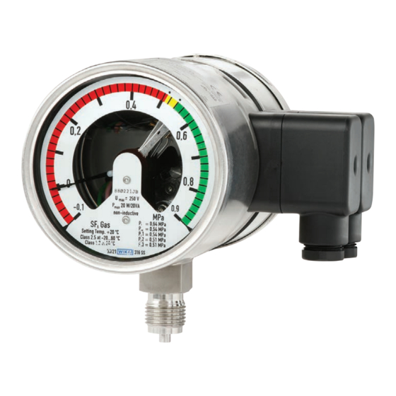
Wherever the gas density of SF gas must be indicated locally and, at the same time, circuits need to be switched, the model GDM-100-T hybrid gas density monitor finds its use. The integrated or attached digital transmitter transmits the parameters of gas density, pressure and temperature as electrical signals via a Modbus RTU protocol. - Page 7 Improper handling or operation of the instrument outside of its technical specifications requires the instrument to be taken out of service immediately and inspected by an authorised WIKA service engineer. The manufacturer shall not be liable for claims of any type based on operation contrary to the intended use.
- Page 8 EN ISO 13732-3 The protective gloves must be worn over the entire period when working on hoses, gas containers (e.g. gas cylinders, tanks) or components which heat up to over 60 °C. WIKA operating instructions, model GDM-100-T...
- Page 9 Read the material safety data sheet of the gas supplier. ■ With large leakage, evacuate the area quickly. ■ Ensure good ventilation. ■ Ensure the leak tightness of the equipment with a leak detector (e.g. model GIR-10). ■ WIKA operating instructions, model GDM-100-T...
- Page 10 SF₆ gas is a colourless and odourless, chemically neutral, inert and non-in- flammable gas which is approx. five times heavier than air, not toxic and not harmful to the ozone layer. Detailed information is given in IEC 60376 and IEC 62271-4. WIKA operating instructions, model GDM-100-T...
- Page 11 3. Safety 3.10 Labelling, safety marks Product label, model GDM-100-T with integrated transmitter (example) Model description Switch contacts: Front cable box Electrical characteristics of the sensor Sensor: rear cable box ...
- Page 12 3. Safety Product label, model GDM-100-T with attached transmitter (example) Model description Model designation of the switch contact Electrical characteristics Switching thresholds Date of manufacture P# product number ...
-
Page 13: Transport, Packaging And Storage
1. Place the instrument, along with the shock-absorbent material, in the packaging. 2. If stored for a prolonged period of time (more than 30 days), place a bag containing a desiccant inside the packaging. WIKA operating instructions, model GDM-100-T... -
Page 14: Commissioning, Operation
When screwing in, do not cross the threads. ■ For parallel threads, use flat gaskets, lens-type sealing rings or WIKA profile sealings at the sealing face . With tapered threads (e.g. NPT threads), sealing is made in the threads , using a suitable sealing material (EN 837-2). - Page 15 Maximum rated operating AC 250 V AC 250 V voltage Ueff Rated operating current Switch-on current Switch-off current Continuous current 0.6 A 0.6 A Maximum switching power 30 W, 50 VA 20 W, 20 VA WIKA operating instructions, model GDM-100-T...
- Page 16 150 mA The switching current must not be less than 20 mA with low voltages for switching relia- bility reasons. For higher loads, and for instruments with liquid-filled cases, WIKA model 905.1X contact protection relays are recommended Overcurrent protectors The instruments do not provide for incorporated overcurrent protectors. Should protec- tors be required, the following values in accordance with EN 60 947-5-1 are to be recommended.
- Page 17 RC element Load Capacitive load With capacitive loads elevated switch-on currents arise. These can be reduced by series-connecting resistors in the supply line. Examples: Contact protection measure with current-limiting resistor Load Load WIKA operating instructions, model GDM-100-T...
- Page 18 Tighten the threaded connection and check that the seal is correctly seated, in order to ensure the ingress protection. Make sure that no moisture enters at the cable end. ■ WIKA operating instructions, model GDM-100-T...
- Page 19 This master controls the entire data ® transfer and monitors any possible timeouts (no reply from the addressed instrument). The connected instruments may only send telegrams after request by means of the master. WIKA operating instructions, model GDM-100-T...
- Page 20 RS-485 Voltage supply 5.5.2 Modbus tool ® The software is available, free-of-charge, from the WIKA website. After wiring and installing the software of the interface converter or copying the Modbus tool software, the program can be started. ® System requirements...
- Page 21 Afterwards, during the reading operation, the entered data becomes visible on the left-hand side. If Windows is used with non-Latin character sets (e.g. Chinese), the area ® settings of the system control must be changed to English (USA), since otherwise, communication problems might occur. WIKA operating instructions, model GDM-100-T...
- Page 22 3.5 characters. The characters within one message may not have spacing of more than 1.5 characters. Examples of a typical transmission: ▶ ▶ Intermission Message 1 Intermission Message 2 Intermission Message 3 ... WIKA operating instructions, model GDM-100-T...
- Page 23 Pressure standardised MPa (gauge Gauge pressure at 20 °C [68 °F] to 20 °C [68 °F] pressure) based on 0.1013 MPa 00090 Pressure standardised Absolute pressure at 20 °C [68 °F] to 20 °C [68 °F] WIKA operating instructions, model GDM-100-T...
- Page 24 Register Parameter Value definition Standard Writable 00100 Address 1 ... 247 00101 Baud rate 1,200 ... 115,200 19,200 00102 Parity None, Even None 00106 Serial number Read only WIKA operating instructions, model GDM-100-T...
- Page 25 Baud rate The different speeds are presented with register values 0 ... 8. Baud rate Register value 1,200 2,400 4,800 9,600 14,400 19,200 5 (standard) 38,400 57,600 115,200 Parity Parity Register value None 0 (standard) Even WIKA operating instructions, model GDM-100-T...
- Page 26 Writing 0x0001 in register 203 causes the transmitter to be reset to its factory settings and a software reset to be carried out. After this process, all writable registers are reset to the initial setting. WIKA operating instructions, model GDM-100-T...
- Page 27 5.6.3 Pin assignment of attached, analogue transmitter (model GD-20-A) Circular connector M12 x 1 (5-pin) Supply voltage Ground 5.6.4 Pin assignment of attached, analogue transmitter with cable outlet (model GD-20-A) Model GD-20-A, with cable outlet UB+/Sig+ Brown Blue 0V/Sig- WIKA operating instructions, model GDM-100-T...
-
Page 28: Faults
▶ Contact the manufacturer. ▶ If a return is needed, please follow the instructions given in chapter 8.2 “Return”. For contact details, see chapter 1 “General information” or the back page of the operating instructions. WIKA operating instructions, model GDM-100-T... - Page 29 With claims, the atmospheric pressure and the temperature during the measurement must be given, as well as the data on the reference standard (model, class). WIKA operating instructions, model GDM-100-T...
-
Page 30: Maintenance, Cleaning And Recalibration
22 kg SF₆ gas and the plant was commissioned after 1st January 2017. With the help of the optional, permanently welded recalibration valve, the gas density monitor can be shut off from the process and recalibrated without having to disassemble it. WIKA operating instructions, model GDM-100-T... -
Page 31: Dismounting, Return And Disposal
Return WARNING! Strictly observe the following when shipping the instrument: All instruments delivered to WIKA must be free from any kind of hazard- ous substances (e.g. decomposition products) and must therefore be cleaned before being returned. When returning the instrument, use the original packaging or a suitable transport packaging. -
Page 32: Specifications
2 magnetic snap-action contacts (option 2) ■ 3 magnetic snap-action contacts (option 3) ■ Switching directions Falling pressure ■ Rising pressure ■ Switching functions Normally closed ■ Normally open ■ Circuits Galvanically connected ■ Galvanically isolated ■ WIKA operating instructions, model GDM-100-T... - Page 33 0 ... 7.5 Pressure ■ 0 … 8 (53.4) 0 … 10.1 Temperature ■ 0 … 10 (68.96) 0 … 12.9 0 … 12 (85.79) 0 … 15.7 0 … 16 (124.64) 0 … 21.3 WIKA operating instructions, model GDM-100-T...
- Page 34 20 °C [68 °F] (g/l SF₆) bar abs. bar abs. 0 ... 2 (12.28) 0 ... 3 (18.65) 14.5 0 ... 6 (38.87) 14.5 0 ... 8 (53.4) 0 ... 10 (68.96) 0 ... 12 (85.79) 0 ... 16 (124.64) WIKA operating instructions, model GDM-100-T...
- Page 35 Gauge pressure based on 1,013 mbar: bar, MPa, kPa, psi, Pa, N/cm ■ Output parameters, analogue version (model GD-20-A) Absolute pressure at 20 °C [68 °F] or gas density in g/l for SF₆ gas as 4 ... 20 mA-current signal WIKA operating instructions, model GDM-100-T...
- Page 36 Immunity against conducted 10 V at 150 kHz to 80 MHz HF signals in accordance with IEC 61000-4-6 4 kV Immunity against fast transients (burst) per IEC 61000-4-4 For further specifications, see the order documentation. WIKA operating instructions, model GDM-100-T...
- Page 37 9. Specifications Dimensions in mm Model GDM-100-T with integrated transmitter and vertical process connection G 1/2 B, rotatable Cable socket Male connector or female con- nector Model GDM-100-T with attached digital transmitter and vertical process connection G 1/2 B WIKA operating instructions, model GDM-100-T...
- Page 38 9. Specifications Model GDM-100-T with integrated transmitter and vertical process connection G 1/2 B with calibration valve Model GDM-100-T with attached digital transmitter and vertical process connection G 1/2 B with calibration valve WIKA operating instructions, model GDM-100-T...
- Page 39 9. Specifications Model GDM-100-T with rear attached digital transmitter and vertical process connection G 1/2 B WIKA operating instructions, model GDM-100-T...
- Page 40 WIKA operating instructions, model GDM-100-T...
- Page 41 1. Allgemeines 2. Aufbau und Funktion 3. Sicherheit 4. Transport, Verpackung und Lagerung 5. Inbetriebnahme, Betrieb 6. Störungen 7. Wartung, Reinigung and Rekalibrierung 8. Demontage, Rücksendung und Entsorgung 9. Technische Daten Konformitätserklärungen finden Sie online unter www.wika.de. WIKA-Betriebsanleitung, Typ GDM-100-T...
-
Page 42: Allgemeines
Es gelten die allgemeinen Geschäftsbedingungen in den Verkaufsunterlagen. ■ Technische Änderungen vorbehalten. ■ Weitere Informationen: ■ - Internet-Adresse: www.wika.de / www.wika.com - zugehörige Datenblätter: SP 60.23 SP 61.16 (Typ GLTC-CV) - Anwendungsberater: Tel.: +49 9372 132-0 Fax: +49 9372 132-406 info@wika.de WIKA-Betriebsanleitung, Typ GDM-100-T... -
Page 43: Aufbau Und Funktion 43 De
2. Aufbau und Funktion 2. Aufbau und Funktion Überblick Hybrid-Gasdichtewächter mit integriertem Hybrid-Gasdichtewächter mit angebautem Transmitter, Typ GDM-100-T Transmitter, Typ GDM-100-T Elektrischer Anschluss Kabeldose vorne: Schaltausgänge Kabeldose hinten: Transmitter Prozessanschluss, Schlüsselfläche Prozessanschluss, Gewinde ... -
Page 44: Sicherheit
Überall dort, wo die Gasdichte von SF₆-Gas vor Ort angezeigt werden muss und gleichzeitig Stromkreise geschaltet werden sollen, findet der Hybrid-Gasdichtewächter Typ GDM-100-T seinen Einsatz. Der integrierte oder angebaute digitale Transmitter überträgt die Parameter Gasdichte, Druck und Temperatur als elektrisches Signal über ein Modbus -RTU-Protokoll. - Page 45 Erste Hilfe und Umweltschutz unterwiesen wird, sowie die Betriebsanleitung und insbesondere die darin enthaltenen Sicherheitshinweise kennt. dass das Gerät gemäß der bestimmungsgemäßen Verwendung für den ■ Anwendungsfall geeignet ist. dass die persönliche Schutzausrüstung verfügbar ist. ■ WIKA-Betriebsanleitung, Typ GDM-100-T...
- Page 46 Schutzhandschuhe gegen Wärme nach EN ISO 13732-1 und gegen Kälte nach EN ISO 13732-3 Die Schutzhandschuhe müssen bei Arbeiten an Schläuchen, Gasbehäl- tern (z. B. Gaszylinder, Tanks) oder Teilen die sich auf über 60 °C erwär- men über die gesamte Dauer hinweg getragen werden. WIKA-Betriebsanleitung, Typ GDM-100-T...
- Page 47 Folgende Sicherheitshinweise beachten, um Gefahren durch Isoliergas zu vermeiden: Persönliche Schutzausrüstung tragen. ■ Das Sicherheitsdatenblatt des Gaslieferanten lesen. ■ Bei großen Leckagen schnell den Ort verlassen. ■ Für gute Belüftung sorgen. ■ Dichtheit der Betriebsmittel mit Leckdetektor sicherstellen (z. B. Typ GIR-10). ■ WIKA-Betriebsanleitung, Typ GDM-100-T...
- Page 48 CIGRE report 276, 2005 (Practical SF₆ gas handling instructions) ■ Information SF₆-Gas ist farb- und geruchlos, chemisch neutral, inert, nicht entflammbar und etwa fünfmal schwerer als Luft, nicht toxisch und nicht ozonschädigend. Detaillierte Angaben befinden sich in der IEC 60376 und IEC 62271-4. WIKA-Betriebsanleitung, Typ GDM-100-T...
- Page 49 3. Sicherheit 3.10 Beschilderung, Sicherheitskennzeichnungen Typenschild, Typ GDM-100-T mit integriertem Transmitter (Beispiel) Typbezeichnung Schaltkontakte: vordere Kabelbox Elektrische Kennwerte des Sensors Sensor: hintere Kabelbox Anschlussbelegung des Sensors ...
- Page 50 3. Sicherheit Typenschild, Typ GDM-100-T mit angebautem Transmitter (Beispiel) Typbezeichnung Typbezeichnung des Schaltkontakts Elektrische Kennwerte Schaltschwellen Herstelldatum P# Erzeugnisnummer Zustand des Schalters bei minimalem Skalenwert ...
-
Page 51: Transport, Verpackung Und Lagerung
Bedingungen erfüllt. Wenn die Originalverpackung nicht vorhanden ist, dann das Gerät wie folgt verpacken und lagern: 1. Das Gerät mit dem Dämmmaterial in der Verpackung platzieren. 2. Bei längerer Einlagerung (mehr als 30 Tage) einen Beutel mit Trocknungsmittel der Verpackung beilegen. WIKA-Betriebsanleitung, Typ GDM-100-T... -
Page 52: Inbetriebnahme, Betrieb
■ Für zylindrische Gewinde sind an der Dichtfläche Flachdichtungen, Dichtlinsen oder WIKA-Profildichtungen einzusetzen. Bei kegeligen Gewinden (z. B. NPT-Gewinde) erfolgt die Abdichtung im Gewinde , mit geeignetem Dichtungswerkstoff (EN 837-2). Das Anzugsdrehmoment ist von der eingesetzten Dichtung abhängig. Um das Messgerät in die Stellung zu bringen, in der es sich am besten ablesen lässt, ist ein Anschluss mit... - Page 53 AC 250 V spannung Ueff Nennbetriebsstrom Einschaltstrom Ausschaltstrom Dauerstrom 0,6 A 0,6 A Maximale Schaltleistung 30 W, 50 VA 20 W, 20 VA Die Grenzwerte nicht überschreiten. Um dauerhaft eine sichere Funktion zu gewährleis- ten, sind folgende Belastungwerte empfohlen: WIKA-Betriebsanleitung, Typ GDM-100-T...
- Page 54 Bei niedrigen Spannungen darf der Schaltstrom aus Gründen der Schaltsicherheit nicht kleiner als 20 mA sein. Für höhere Belastungen, sowie für Geräte mit flüssigkeitsgefüllten Gehäusen, werden WIKA-Kontaktschutzrelais Typen 905.1X empfohlen Überstrom-Schutzeinrichtungen In den Geräten sind keine Überstrom-Schutzeinrichtungen eingebaut. Falls Schutzein- richtungen gefordert werden, sind folgende Werte nach EN 60 947-5-1 zu empfehlen.
- Page 55 VDR Last Beispiel: Kontakt- schutzmaßnahme mit RC-Glied Last Kapazitive Last Bei kapazitiven Lasten treten erhöhte Einschaltströme auf. Diese können durch Reihen- schalten von Widerständen in der Zuleitung verringert werden. Beispiele: Kontaktschutzmaßnahme mit Widerstand zur Strombegrenzung Last Last WIKA-Betriebsanleitung, Typ GDM-100-T...
- Page 56 Kabeldose korrekt sitzt und dass die Dichtungen vorhanden und nicht beschädigt sind. Verschraubung festziehen und den korrekten Sitz der Dichtun- gen überprüfen, um die Schutzart zu gewährleisten. Sicherstellen, dass am Ende des Kabels keine Feuchte eintritt. ■ WIKA-Betriebsanleitung, Typ GDM-100-T...
- Page 57 Signal zwischen den Pins 4 und 5 (A und B) ausgewertet. Modbus ® Das Modbus -Kommunikationsprotokoll basiert auf einer Master/Slave-Architektur. Das ® beim Gasdichtesensor des Typs GD-20 implementierte Protokoll ist Modbus -RTU mit ® serieller Übertragung über eine 2-Draht RS-485-Schnittstelle. WIKA-Betriebsanleitung, Typ GDM-100-T...
- Page 58 5.5.1 Verbindung mit dem PC herstellen Schnittstellenwandler RS-485 Spannungsversorgung 5.5.2 Modbus -Tool ® Die Software ist auf der WIKA Homepage kostenlos verfügbar. Nach dem Verkabeln und der Softwareeinrichtung des Schnittstellenwandlers bzw. Kopieren der Modbus -Tool-Software kann das Programm gestartet werden. ® WIKA-Betriebsanleitung, Typ GDM-100-T...
- Page 59 Beim anschließenden Lesevorgang sind die eingetragenen Daten auf der linken Seite sichtbar. Wird Windows mit nicht-lateinischen Zeichensätzen (z. B. chinesisch) ® verwendet, so muss in den Gebietseinstellungen der Systemsteuerung Englisch (USA) eingestellt werden, da ansonsten Kommunikationsproble- me auftreten können. WIKA-Betriebsanleitung, Typ GDM-100-T...
- Page 60 -Spezifikation muss zwischen zwei Telegrammen eine Pause von ® mindestens 3,5 Zeichen eingehalten werden. Innerhalb eines Telegramms dürfen die einzelnen Zeichen nicht mehr als 1,5 Zeichen Abstand aufweisen. Beispiel einer typischen Übertragung: ▶ ▶ Pause Telegramm 1 Pause Telegramm 2 Pause Telegramm 3 ... WIKA-Betriebsanleitung, Typ GDM-100-T...
- Page 61 1.013 mbar 00060 Druck normiert auf Absolutdruck bei 20 °C [68 °F] 20 °C [68 °F] 00062 Druck normiert auf Realtivdruck bei 20 °C [68 °F] bezo- 20 °C [68 °F] (Relativdruck) gen auf 0,1013 MPa WIKA-Betriebsanleitung, Typ GDM-100-T...
- Page 62 Konfiguration ab Werk kann vom hier beschriebenen Standard abweichen. Register Parameter Wertedefinition Standard Beschreibbar 00100 Adresse 1 ... 247 00101 Baudrate 1.200 ... 115.200 19.200 Parität None, Even None 00102 00106 Seriennummer Nur Lesen 00110 HW-Version Nur Lesen 00111 SW-Version Nur Lesen WIKA-Betriebsanleitung, Typ GDM-100-T...
- Page 63 Die unterschiedlichen Geschwindigkeiten werden mit Registerwerten von 0 ... 8 dargestellt. Baudrate Registerwert 1.200 2.400 4.800 9.600 14.400 19.200 5 (Standard) 38.400 57.600 115.200 Parität Parität Registerwert None 0 (Standard) Even TAG-Nummer Hier kann ein 16 Zeichen langer Transmittername eingegeben werden. WIKA-Betriebsanleitung, Typ GDM-100-T...
- Page 64 Prozess sind alle veränderten Parameter wirksam (z. B. Änderung der Adresse). Zurücksetzen auf Werkseinstellungen Durch Schreiben von 0x0001 in das Register 203 wird der Transmitter auf Werkseinstellungen zurückgesetzt und ein Softwarereset durchgeführt. Nach diesem Prozess sind alle beschreibbaren Register auf die Grundeinstellung zurückgesetzt. WIKA-Betriebsanleitung, Typ GDM-100-T...
- Page 65 Sicherstellen, dass am Ende des Kabels keine Feuchte eintritt. ■ 5.6.3 Anschlussbelegung angebauter, analoger Transmitter (Typ GD-20-A) Rundstecker M12 x 1 (5-polig) Hilfsenergie Masse 5.6.4 Anschlussbelegung angebauter, analoger Transmitter mit Kabelausgang (Typ GD-20-A) Typ GD-20-A, mit Kabelausgang UB+/Sig+ Braun Blau 0V/Sig- WIKA-Betriebsanleitung, Typ GDM-100-T...
-
Page 66: Störungen
Sicherstellen, dass kein Druck bzw. Signal mehr anliegt und gegen versehentliche Inbetriebnahme schützen. ▶ Kontakt mit dem Hersteller aufnehmen. ▶ Bei notwendiger Rücksendung die Hinweise unter Kapitel 8.2 „Rücksendung“ beachten. Kontaktdaten siehe Kapitel 1 „Allgemeines“ oder Rückseite der Betriebs- anleitung. WIKA-Betriebsanleitung, Typ GDM-100-T... - Page 67 Bei Reklamationen sind die Fertigungs- und Erzeugnisnummern anzugeben. Die Fertigungsnummer ist auf dem Ziffernblatt angebracht, die Erzeugnisnummer auf dem Typenschild. Bei Reklamationen ist stets der Luftdruck und die Temperatur während der Messung anzugeben, ebenso die Daten des Vergleichsnormals (Typ, Klasse). WIKA-Betriebsanleitung, Typ GDM-100-T...
-
Page 68: Wartung, Reinigung And Rekalibrierung
EU-Verordnung Nr. 517/2014 über fluorierte Treibhausgase sieht eine Kontrolle des Leckage-Erkennungssystems rechtlich verpflichtend mindestens alle 6 Jahre vor, falls mehr als 22 kg SF₆-Gas enthalten sind und die Anlage nach dem 1. Januar 2017 in Betrieb genommen wurde. WIKA-Betriebsanleitung, Typ GDM-100-T... -
Page 69: Demontage, Rücksendung Und Entsorgung
Schutzausrüstung“). Rücksendung WARNUNG! Beim Versand des Gerätes unbedingt beachten: Alle an WIKA gelieferten Geräte müssen frei von Gefahrstoffen (z. B. Zersetzungsprodukten) sein und sind daher vor der Rücksendung zu reinigen. Zur Rücksendung des Gerätes die Originalverpackung oder eine geeignete Transportverpackung verwenden. -
Page 70: Technische Daten
2 kV, 50 Hz, 1 s 100 % Technische Daten der Schaltkontake Anzahl Schaltkontakte 1 Magnetspringkontakt (Option 1) ■ 2 Magnetspringkontakte (Option 2) ■ 3 Magnetspringkontakte (Option 3) ■ Schaltrichtungen Fallender Druck ■ Steigender Druck ■ Schaltfunktionen Öffner ■ Schließer ■ WIKA-Betriebsanleitung, Typ GDM-100-T... - Page 71 0 ... 6 (38,87) 0 ... 7,5 Druck ■ 0 … 8 (53,4) 0 … 10,1 Temperatur ■ 0 … 10 (68,96) 0 … 12,9 0 … 15,7 0 … 12 (85,79) 0 … 16 (124,64) 0 … 21,3 WIKA-Betriebsanleitung, Typ GDM-100-T...
- Page 72 20 °C [68 °F] bar abs. (g/l SF₆) 0 ... 2 (12,28) 0 ... 3 (18,65) 14,5 0 ... 6 (38,87) 14,5 0 ... 8 (53,4) 0 ... 10 (68,96) 0 ... 12 (85,79) 0 ... 16 (124,64) WIKA-Betriebsanleitung, Typ GDM-100-T...
- Page 73 Absolutdruck: bar, MPa, kPa, psi, Pa, N/cm ■ Relativdruck basierend auf 1.013 mbar: bar, MPa, kPa, psi, Pa, N/cm ■ Ausgangsparameter, analoge Ausführung (Typ GD-20-A) Absolutdruck bei 20 °C [68 °F] oder Gasdichte in g/l für SF₆-Gas als 4 ... 20 mA-Stromsignal WIKA-Betriebsanleitung, Typ GDM-100-T...
- Page 74 ESD nach IEC 61000-4-2 kV indirekte Entladung Störfestigkeit gegen leitungsgeführte 10 V bei 150 kHz bis 80 MHz HF-Signale nach IEC 61000-4-6 Störfestigkeit gegen schnelle Tran- 4 kV sienten (Burst) nach IEC 61000-4-4 Weitere technische Daten siehe Bestellunterlagen. WIKA-Betriebsanleitung, Typ GDM-100-T...
- Page 75 9. Technische Daten Abmessungen in mm Typ GDM-100-T mit integriertem Transmitter und vertikalem Prozessanschluss G 1/2 B, drehbar Kabeldose oder Stecker male Stecker female Typ GDM-100-T mit angebautem digitalen Transmitter und vertikalem Prozessanschluss G 1/2 B WIKA-Betriebsanleitung, Typ GDM-100-T...
- Page 76 9. Technische Daten Typ GDM-100-T mit integriertem Transmitter und vertikalem Prozessanschluss G 1/2 B mit Kalibrierventil Typ GDM-100-T mit angebautem digitalen Transmitter und vertikalem Prozessanschluss G 1/2 B mit Kalibrierventil WIKA-Betriebsanleitung, Typ GDM-100-T...
- Page 77 9. Technische Daten Typ GDM-100-T mit angebautem digitalen Transmitter rückseitig und vertika- lem Prozessanschluss G 1/2 B WIKA-Betriebsanleitung, Typ GDM-100-T...
- Page 78 WIKA-Betriebsanleitung, Typ GDM-100-T...
- Page 79 WIKA-Betriebsanleitung, Typ GDM-100-T...
- Page 80 Further WIKA subsidiaries worldwide can be found online at www.wika.com. Weitere WIKA-Niederlassungen weltweit finden Sie online unter www.wika.de. WIKA Alexander Wiegand SE & Co. KG Alexander-Wiegand-Straße 30 63911 Klingenberg • Germany Tel. +49 9372 132-0 Fax +49 9372 132-406 info@wika.de www.wika.de...
Need help?
Do you have a question about the GDM-100-T and is the answer not in the manual?
Questions and answers