Table of Contents
Advertisement
Quick Links
IX. Replacement Parts
Threaded ring
Acrylic window
Instrument glass window
Laminated safety glass window
Restrictor (SS) (0.6 mm I.D.) standard
Restrictor (SS) (0.3 mm I.D.) "super"
Restrictor (Monel
) (0.6 mm I.D.)
®
Restrictor (brass) (0.6 mm I.D.)
Window o-ring
Adjustable pointer
Case (blow-out back separate)
Fill plug
Vent plug
Socket o-ring
Blow-out back (LM)
Back o-ring (for dry gauges)
Membrane LM (for glycerine or silicone)
Membrane LM (for fluorocarbon)
Membrane LBM (for glycerine or silicone)
Filling kit LM (for glycerine & silicone)
Filling kit LM (for fluorocarbon)
Filling kit LBM (for glycerine & silicone)
Movement for vacuum ranges
Movement for 15 psi to 60 psi
Movement for 100 psi and up
X. Warning
Pressure gauges must be selected and installed so that the possibility of failure resulting in injury or damage
caused by misuse or misapplication is minimized. For correct selection and use of gauges, refer to ASME B40.1,
which can be obtained from The American Society of Mechanical Engineers, Three Park Avenue, New York, NY
10016 - 5990. Important factors for proper gauge selection are:
Process: Wetted parts must be compatible with the measured media.
Pressure: The range of the gauge should generally be twice the working pressure. The working pressure in all
cases should be limited to 75% of the gauge range. Where alternating pressure and pulsation are encountered,
working pressure should be limited to 2/3 of the gauge range.
Pulsation / Vibration: Pressure pulsation and vibration could result in fatigue failure of the measuring system.
Therefore, dampening provisions such as liquid filling of the gauge, installing flow restricting devices or isolating
from the vibration source should be considered.
Temperature: Excessive temperature exposure may result in damage to the measuring system and/or gauge
outer parts, case, gasket, and window. Preventive temperature lowering devices such as the WIKA cooling ele-
ment or a pigtail siphon should be considered.
Liquid Fill: Be sure that the filling liquid can safely mix with the process fluid.
WIKA Instrument Corporation
1000 Wiegand Boulevard
Lawrenceville, Georgia 30043-5868
1-888-WIKA USA, (770) 513-8200 (in Georgia)
http://www.wika.com
In keeping with and for purposes of product improvement,
WIKA reserves the right to make design changes without notice.
Instruction Sheet – 03/10
P/N 2207290 Rev 5
4½"
6"
2086000
4006755
4000021
2246104
0561134
1111710
0561150
0154075
0029122
0029122
0165514
0165514
0607797
0607797
4324
4324
0564354
2016818
2087431
1656244
2085993
4006747
0589705
0589705
0659835
0659835
1063707
1063707
2086018
2247283
2208741
2208741
1053019
1053019
1095390
1095390
1654250
1654250
1126768
1126768
1126776
1126776
2044480
2044480
4001842
2054761
4001851
2019868
4001869
2091941
FAX (770) 338-5118
Instruction Sheet available at http://www.wika.com
Operating & Installation
Instructions
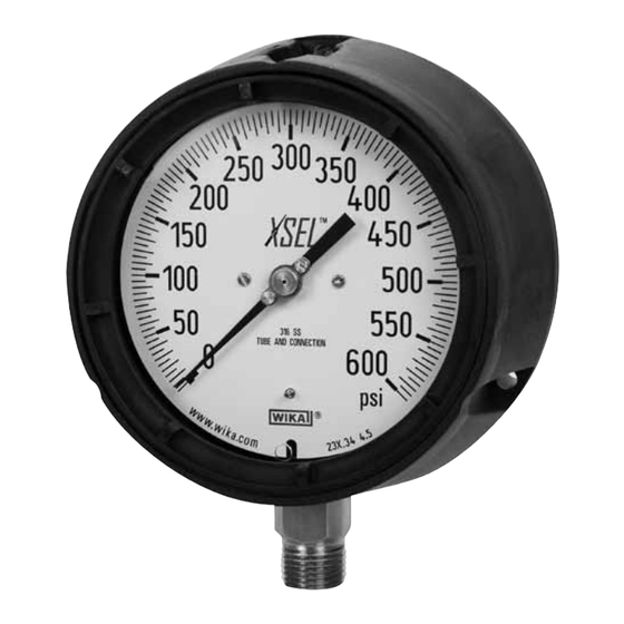
XSEL
Process Gauge
TM
Type 2XX.34
SIZE 4½" & 6" SOLID FRONT
Revision Date: March 1, 2010
R
Advertisement
Table of Contents

Related Manuals for WIKA 2XX.34


Summary of Contents for WIKA 2XX.34
- Page 1 Temperature: Excessive temperature exposure may result in damage to the measuring system and/or gauge outer parts, case, gasket, and window. Preventive temperature lowering devices such as the WIKA cooling ele- ment or a pigtail siphon should be considered.
- Page 2 60 psi or less, the pointer must built to deliver long and reliable WIKA or your local distributor for a you will need to use the Pointer To assemble the dial, place it back...
Need help?
Do you have a question about the 2XX.34 and is the answer not in the manual?
Questions and answers