Table of Contents
Advertisement
Quick Links
Technical information
Assembly instructions
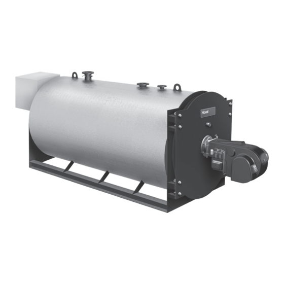
Oil/Gas condensing boiler
Max-3 condens (3000-5000), Max-3 condens E (3000-5000)
Hoval products must be installed and commissioned
by specialists only. These instructions are intended
for service engineers. Electrical installation must be
performed by a licensed electrical company.
Subject to modifi cations
|
4 215 983 / 01 - 10/21
These instructions are applicable
to the following types:
2-Max-3 condens
(3000)
2-Max-3 condens
(4000)
2-Max-3 condens
(5000)
2-Max-3 condens E
(3000)
2-Max-3 condens E
(4000)
2-Max-3 condens E
(5000)
EN
Advertisement
Table of Contents

Subscribe to Our Youtube Channel
Related Manuals for Hoval 2-Max-3 condens


Summary of Contents for Hoval 2-Max-3 condens
- Page 1 (3000) 2-Max-3 condens E (4000) 2-Max-3 condens E (5000) Hoval products must be installed and commissioned by specialists only. These instructions are intended for service engineers. Electrical installation must be performed by a licensed electrical company. Subject to modifi cations...
-
Page 2: Table Of Contents
TABLE OF CONTENTS Important notices General safety instructions ..............................3 Explanation of the symbols ..............................3 1.2.1 Warnings ..................................3 1.2.2 Warning symbols................................3 1.2.3 Information ..................................3 On delivery ...................................4 Warranty ....................................4 Manuals ....................................4 Regulations, official approvals ............................4 1.6.1 Germany § ..................................4 1.6.2 Austria § ...................................4 1.6.3 Switzerland §... -
Page 3: Important Notices
IMpORTanT nOTICES Important notices Explanation of the symbols 1.2.1 Warnings General safety instructions The system may only be placed in operation DANGER if all the relevant standards and safety reg u la ... indicates a situation of immediate danger tions have been complied with. which will lead to serious or fatal injuries if not avoided. -
Page 4: On Delivery
• ÖVGW TRgas (Austrian Gas and Water Confederation All instructions relevant to your system can be found in Technical Guidelines) the Hoval system manual please keep all manuals! In exceptional cases, the instructions can be found with the components! 1.6.3... -
Page 5: Installation
The flue gas condensate must be introduced into the public sewer network as prescribed. Neutralisation equipment might be needed please contact the nearest Hoval branch. In particular with oil-firing, the use and suitability of the neutralisation equipment must be taken into account. -
Page 6: Technical Information
TECHnICaL InFORMaTIOn Technical information Description of the boiler The Max3 condens and Max3 condens E condensing boiler is constructed in 3compartment form. The heating gases flow from the cylindrical combustion chamber into the water-cooled reversing chamber and through the 2nd compartment into the front reversing chamber. -
Page 7: Technical Data
TECHnICaL InFORMaTIOn Technical data 3.2.1 Max-3 condens (3000-5000) for natural gas H Type (3000) (4000) (5000) Fuel Natural gas H Natural gas H Natural gas H • Nominal heat output at 80/60 °C 3750 5006 6285 • Nominal heat output at 80/30 °C 3951 5283 6636... -
Page 8: Max-3 Condens (3000-5000) For El Low-Sulphur Fuel Oil (Sulphur Content < 50 Mg/Kg)
TECHnICaL InFORMaTIOn 3.2.2 Max-3 condens (3000-5000) for EL low-sulphur fuel oil (sulphur content < 50 mg/kg) Type (3000) (4000) (5000) Fuel EL fuel oil EL fuel oil EL fuel oil low-sulphur low-sulphur low-sulphur • Nominal heat output at 80/60 °C 3750 5006 6285... -
Page 9: Max-3 Condens E (3000-5000) For Natural Gas H
TECHnICaL InFORMaTIOn 3.2.3 Max-3 condens E (3000-5000) for natural gas H Type (3000) (4000) (5000) Fuel Natural gas H Natural gas H Natural gas H • Nominal heat output at 80/60 °C 3162 4215 5305 • Nominal heat output at 80/30 °C 3412 4546 5732... -
Page 10: Max-3 Condens E (3000-5000) For El Eco Fuel Oil
TECHnICaL InFORMaTIOn 3.2.4 Max-3 condens E (3000-5000) for EL eco fuel oil Type (3000) (4000) (5000) Fuel EL low-sulphur fuel oil/EL eco fuel oil • Nominal heat output at 80/60 °C 3162 4215 5305 • Nominal heat output at 80/30 °C 3325 4431 5578... -
Page 11: Dimensions
TECHnICaL InFORMaTIOn Dimensions View A 3.3.1 Max-3 condens (3000-5000) (Dimensions in mm) Boiler supply PN 16 (3000,4000) DN 200 Safety valve fitting PN 16 (3000,4000) DN 80 (5000) DN 250 (5000) DN 100 Boiler return PN 16 (3000,4000) DN 200 Sight glass (5000) DN 250... -
Page 12: Max-3 Condens E (3000-5000)
TECHnICaL InFORMaTIOn 3.3.2 Max-3 condens E (3000-5000) View A The control can be fitted on the right (Dimensions in mm) or left side. Boiler supply PN 16 (3000,4000) DN 200 Safety valve fitting PN 16 (3000,4000) DN 80 (5000) DN 250 (5000) DN 100 Boiler return PN 16... -
Page 13: Installation
InSTaLLaTIOn Installation Flue gas connection and dimensioning To guarantee economical and faultfree operation, boiler Boiler room requirements and flue gas system must be mutually adapted to create The valid building supervisory regulations for the in stal a functional unit. la tion location are applicable for the construction re quire ments for boiler rooms and their aeration and ventilation. -
Page 14: Installing Burner Max-3 Condens And Max-3 Condens E (3000-5000)
InSTaLLaTIOn Installing burner Max-3 condens Noise damping Gas pipelines are to be installed so that no vibrations and Max-3 condens E (3000-5000) can be transferred to the building. For burner connection dimensions, see The burner can be covered with a noisedamping hood. chapter “3.3 Dimensions”, page 11. -
Page 15: Fuel
InSTaLLaTIOn Max-3 condens E heating gas-side resistance (4000) (3000) (5000) 1200 1500 1800 2100 2400 2700 3000 3300 3600 3900 4200 4500 4800 5100 5400 5700 Kesselleistung (kW) Boiler output (kW) kW = Heizkesselleistung = Boiler output Boiler output Kesselvorlauftemperatur 80°C, Rücklauftemperatur 60°C mbar = Flue gas resistance =1.14 (Natural gas: CO = 10.5 Boiler flow temperature 80 °C, return temperature 60 °C... -
Page 16: Flue Gas And Output Diagram
InSTaLLaTIOn Flue gas and output diagram 4.4.1 Max-3 condens (3000-5000) flue gas and output diagram Max-3 condens (VL 80 °C / RL 60 °C) flue gas and output diagram (5000) (3000) (4000) 1200 1500 1800 2100 2400 2700 3000 3300 3600 3900 4200... -
Page 17: Max-3 Condens E (3000-5000) Flue Gas And Output Diagram
InSTaLLaTIOn 4.4.2 Max-3 condens E (3000-5000) flue gas and output diagram Max-3 condens E (VL 80 °C / RL 60 °C) flue gas and output diagram (4000) (5000) (3000) 1200 1500 1800 2100 2400 2700 3000 3300 3600 3900 4200 4500 4800 5100... -
Page 18: Minimum Value Limiting Of Boiler Return Temperature
InSTaLLaTIOn Minimum value limiting of boiler Setting the temperature controllers return temperature Basic setting of the controller is carried out by the heating contractor. Hydraulic and control measures must be provided to en sure that the temperatures do not fall below the per mis si ble minimum boiler flow and return temperature under Safety valves any operating conditions. -
Page 19: Commissioning
• As a rule, untreated domestic water is best suited as Water quality fil ling and replacement water for a system with Hoval boil ers. However, the quality of the untreated mains • Hoval boilers and calorifiers are suitable for heating sys-... -
Page 20: Filling The Calorifier
COMMISSIOnInG Filling the calorifier (if fitted) The boiler may be put into operation even when the calori fier is not filled. Commissioning Important: At the time of initial commissioning, check that all safety and control devices are functioning properly (in ac cor dance with the operating instructions). -
Page 21: Maintenance (Only For Boiler Controller With Toptronic ® E Control)
MaInTEnanCE (OnLy FOR BOILER COnTROLLER WITH TOpTROnIC® E COnTROL) Maintenance (only for boiler controller with TopTronic E control) ® Information for combustion controller / chimney sweep regarding emission monitor key This chapter is exclusively intended to describe the function of emissions and manual operation settings for the fi ring monitoring technician / chimney sweep. -
Page 22: Cleaning
MaInTEnanCE (OnLy FOR BOILER COnTROLLER WITH TOpTROnIC® E COnTROL) Cleaning Insufficient cleaning not only leads to increased fuel con- sumption, it also shortens the operating time of the boiler. CAUTION The boiler must be cleaned at least 1 x per year by a chimney sweep. -
Page 23: Cleaning The Flue Gas Heat Exchanger
MaInTEnanCE (OnLy FOR BOILER COnTROLLER WITH TOpTROnIC® E COnTROL) Cleaning the flue gas heat exchanger NOTICE In principle, the cleaning intervals conform with the local a. When wet cleaning the heat exchanger, it regulations. must be ensured that the cleaning solution can drain away (through the condensate To prevent malfunctions, we recommend checking the drainage line of the heat exchanger or... - Page 24 4 215 983 / 01...
- Page 25 4 215 983 / 01...
- Page 26 COPY FOR PLANT USER Confirmation The user (owner) of the system herewith confi rms that • he has received adequate instruction in the operating and maintenance of the installation, • received and taken note of the operating and maintenance instructions and, where applicable other documents con- cerning the installation and any further components.
Need help?
Do you have a question about the 2-Max-3 condens and is the answer not in the manual?
Questions and answers