
Subscribe to Our Youtube Channel
Related Manuals for SHS EtherCAT HT7


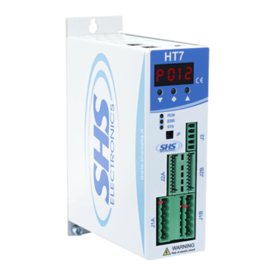
Summary of Contents for SHS EtherCAT HT7
- Page 1 Stepper Motor Drive EtherCAT User Manual Manual r06 Company Quality Assurance conforming S.H.S. s.r.l. Via Fratelli Rosselli 29 - 20027 Rescaldina (MI) Italy - Phone +39 0331 466918 - www.shsitalia.it...
- Page 2 Index Introduction Warnings General Info Configuration File Device Control Drive State Device Control Commands Errors Device Errors Communication Errors System Units Operating Modes Overview Profile position mode (pp) Overview Controlword Profile Position mode-specific bits Statusword Profile Position mode-specific bits Profile velocity mode (pv) Overview Controlword Profile Velocity mode-specific bits Statusword Profile Velocity mode-specific bits...
-
Page 3: Table Of Contents
Digital inputs Digital outputs Analog input Analog output EtherCAT communication EtherCAT State Machine Object Dictionary Overview Object Dictionary Overview Object Data Types Object Access Types Objects Device type 0x1000 Error Register 0x1001 Manufacturer Device Name 0x1008 Hardware Version Object 0x1009 Software Version Object 0x100A Identity Object 0x1018 Error Settings Object 0x10F1... - Page 4 Digital Inputs Configuration Object 0x2070 Digital Inputs Functionalities Object 0x2071 Digital Outputs Configuration Object 0x2078 Digital Outputs Functionalities Object 0x2079 Error Code Object 0x603F Controlword Object 0x6040 Statusword Object 0x6041 Quick Stop Option Code Object 0x605A Shutdown Option Code Object 0x605B Disable Operation Option Code Object 0x605C Modes of Operation Object 0x6060 Modes of Operation Display Object 0x6061...
- Page 5 Touch Probe Position 1 Negative Value Object 0x60BB Touch Probe 1 Positive Edge Counter Object 0x60D5 Touch Probe 1 Negative Edge Counter Object 0x60D6 Supported Homing Methods Object 0x60E3 Motor Resolution Object 0x60EF Position Demand Internal Value Object 0x60FC Target Velocity Object 0x60FF Supported Drive Modes Object 0x6502 HT7 Ethercat User Guide...
- Page 6 1 Introduction Warnings This document is meant for qualified technical personnel. You must read carefully and understand the manual, then follow the instruction given here before starting any activities. General Info This document provides the necessary information to use the HT7 stepper motor drive by mean of EtherCAT communication.
- Page 7 2 Device Control The state machine describes the drive states and the possible transition among them. Each state determines a drive behavior and the accepted control commands. The drive state can be read by means of the Statusword, while the transitions can be automatic or acted by the Controlword. Not ready to Switch On state is performed automatically by the driver during startup.
- Page 8 Drive State The current state of the driver can be read by the following bits of the Statusword. State Statusword (binary) Description Start xxxx xx0x x000 0000 Bootup Not ready to Switch On xxxx xx1x x000 0000 Drive is disabled Drive initialization completed Switch On Disabled xxxx xx1x x100 0000...
- Page 9 3 Errors Device Errors When the drive detects an error, it generates an error code. The reaction to an error depends on error type and option code. After execution of the fault reaction, the device changes to fault state and the drive will be disabled.
- Page 10 Abort Code Name Data cannot be transferred or saved in the application due to device 0x 0800 0022 state Dynamic generating of the object directory failed or no object 0x 0800 0023 directory available Table 3-1 Abort Codes Description 4 System Units The drive uses fixed internal drive units to manage the movements, nevertheless user can act on some parameters in order to have convenient physical units, as explained on this section.
- Page 11 Mode of operation Abbreviation Code Profile velocity mode Homing mode Table 5- 1 Supported operation modes The supported modes are listed in the object Supported drive modes. Profile position mode (pp) 5.2.1 Overview When the drive is in pp mode, the position control loop is closed on the drive side. The control device can manage the positioning by acting on the objects shown in Figure 5-1 below.
- Page 12 Figure 5- 2 Set-point example 5.2.2 Controlword Profile Position mode-specific bits The profile position mode uses some bits of the Controlword for mode-specific purposes, as highlighted on Table 5-2 explain the usage of these bits. Value Definition 0 → 1 New Setpoint, start move Target position is an absolute value Target position is a relative value Positioning shall be executed or continued...
- Page 13 Value Definition Target position not reached Target position reached Previous setpoint already processed Previous setpoint still in process, setpoint can be overwritten No following error Following error Table 5-4 Statusword bits 10, 12, 13 in pp mode Profile velocity mode (pv) 5.3.1 Overview When the drive is in pv mode, the position control loop is closed on the drive side.
- Page 14 5.3.2 Controlword Profile Velocity mode-specific bits The profile velocity mode uses Halt bit 8 of the Controlword for mode-specific purposes, as highlighted on Table 5-5. Bit 5 Definition The motion shall be executed or continued Motor shall be stopped accordingly to halt option code object (0x605D) Table 5- 5 Controlword bit 8 in pv mode 5.3.3 Statusword Profile Velocity mode-specific bits The profile position mode uses some bits of the Statusword for mode-specific purposes, Table 5-6...
- Page 15 Homing mode (hm) 5.4.1 Overview This operation mode is used to make the drive seek for the zero (homing) position. Figure 5-8 shows the objects involved in this functionality. The home position and the zero position are offset by the home offset. Actually, HT7 drive supports the methods described in the following sections and available on the object Supported homing methods.
- Page 16 5.4.4 Homing Method 1 (Negative Limit Switch with Encoder Index) After the Homing operation start bit has been set, the drive starts the motor in CCW direction (toward the negative position), until the negative limit switch is reached, then it moves in positive direction to disengage the switch.
- Page 17 6 Encoder Feedback A digital encoder sensor can be connected to the drive, both single ended and differential sensors are accepted; wiring instructions are available into the hardware manual. The behavior of the drive when the encoder is used is configured by the Encoder Mode sub-index of the Encoder Configuration Object 0x2032.
-
Page 18: Digital Inputs
7 Inputs and Outputs Digital inputs Digital inputs can be mapped to predefined functions or as general-purpose inputs, by mean of the Digital Inputs Configuration Object 0x2070. By modifying the Digital Inputs Functionalities Object 0x2071, the polarity can be set-up for all the functions, while only the general-purpose inputs can be masked. -
Page 19: Digital Outputs
Digital outputs Digital outputs (OUT1, OUT2 and OUT3) can be mapped as general-purpose outputs, by mean of the Digital Outputs Configuration Object 0x2078. The value and the mask can be set modifying the Digital Outputs Functionalities Object 0x2079. Analog input Analog inputs can’t be read or assigned to a function by the control device. -
Page 20: Ethercat Communication
8 EtherCAT communication EtherCAT State Machine The EtherCAT State Machine in Figure 8-1 indicates which functionalities are actually available. The functions in the different states are described in Table 8-1below. Transitions among states are described in Table 8-2. Figure 8-1 EtherCAT Slave State Machine State Description INIT... - Page 21 Transition Description Start of cyclic communication. P -> S Master configures parameters using mailbox communication. Master requests SafeOp state and waits for confirmation. S -> O Master sends valid Outputs and requests Op state Error Init Incorrect ESC register configuration (DC, FMMU, SyncManager, etc.). Error PreOp The AL Status Code register (register 0x134) indicates error reasons.
-
Page 22: Object Dictionary
9 Object Dictionary Overview 9.1.1 Object Dictionary Overview Index Name Data type Access 0x1000 Device Type UINT32 0x1001 Error Register UINT8 0x1008 Manufacturer Device Name STRING 0x1009 Hardware Version STRING 0x100A Software Version STRING 0x1018 Identity Object RECORD 0x10F1 Error Setting RECORD 0x1600 Receive PDO 1 Mapping... -
Page 23: Object Data Types
Index Name Data type Access 0x6061 Modes of operation display INT8 0x6062 Position Demand Value INT32 0x6063 Position actual internal value INT32 0x6064 Position actual value INT32 0x606B Velocity Demand Value INT32 0x606C Velocity Actual Value INT32 0x606D Velocity window UINT16 0x606E Velocity window time... -
Page 24: Object Access Types
Type Description Size [bits] Range INTEGER16 Signed integer -32768 … 32767 INTEGER32 Signed integer -2147483648 … 2147483647 UNSIGNED8 Unsigned integer 0 … 255 UNSIGNED16 Unsigned integer 0 … 65535 UNSIGNED32 Unsigned integer 0 … 4294967265 UNSIGNED64 Unsigned integer 0 … 18446744073709551615 VISIBLE_STRING Array of n char n * 8... -
Page 25: Manufacturer Device Name 0X1008
Attribute Value Name Error Register Index 0x1001 Subindex 0x00 Type UNSIGNED8 Access Default Value Value range Table 9- 5 Object 0x1001 Error Register Description Motion Error Reserved Profile specific Communication Error Overtemperature Error Voltage Error Current Error Generic Error Table 9-6 Error Register Bits 9.2.3 Manufacturer Device Name 0x1008 Product name: “HT7x0_ECAT”... -
Page 26: Software Version Object 0X100A
VISIBLE_STRING Access Default Value Value range Table 9-9 Object 0x100A Software Version 9.2.6 Identity Object 0x1018 This object contains SHS vendor identification number, assigned by ETG, the product code, HW version and SW version. Attribute Value Name Identity Object Index... -
Page 27: Error Settings Object 0X10F1
Attribute Value Subindex 0x02 Type UNSIGNED32 Access Default Value Value range Table 9-12 Object 0x1018 sub2 Product Code The high word contains the software version. The low word contains the application version of the version array. Attribute Value Name Revision Number Index 0x1018 Subindex... -
Page 28: Receive Pdo 1 Mapping Object 0X1600
Attribute Value Access Default Value Value range Table 9-15 Object 0x10F1 sub1 Local Error Reacrion Attribute Value Name Sync Error Counter Limit Index 0x10F1 Subindex 0x02 Type UNSIGNED16 Access Default Value Value range Table 9-16 Object 0x10F1 sub2 Sync Error Counter Limit 9.2.8 Receive PDO 1 Mapping Object 0x1600 PDO mapping can be changed. -
Page 29: Transmit Pdo 1 Mapping Object 0X1A00
Attribute Value Type UNSIGNED8 Access Default Value Value range Sub-index Access Default value Mapped Object 0x01 0x60400010 Controlword 0x02 0x607A0020 Target position 0x03 0x60FF0020 Target Velocity 0x04 0x60830020 Profile acceleration 0x05 0x60810020 Profile velocity 0x06 0x60980008 Homing Method 0x07 0x60600008 Modes of operation 0x08 0x20790110... -
Page 30: Sync Manager Communication Type Object 0X1C00
Attribute Value Name Transmit PDO 256 Mapping Index 0x1B00 Subindex 0x00 Type UNSIGNED8 Access Default Value Value range Sub-index Access Default value Mapped Object 0x01 0x60410010 Statusword 0x02 0x60640020 Position actual value 0x03 0x606C0020 Velocity Actual Value 0x04 0x60610008 Modes of operation display 0x05 0x20710110 Digital Inputs Functionalities State... -
Page 31: Sync Manager Channel 2 (Rxpdo) Object 0X1C12
Attribute Value Subindex 0x01 Type UNSIGNED8 Access Default Value 1: Mailbox Receive (Master -> Slave) Table 9-27 Communication Type Sync Channel 0 Attribute Value Name Communication Type Sync Channel 1 Index 0x1C00 Subindex 0x02 Type UNSIGNED8 Access Default Value 2: Mailbox Transmit (Master <- Slave) Table 9-28 Communication Type Sync Channel 1 Attribute Value... -
Page 32: Sync Manager Channel 3 (Txpdo) Object 0X1C13
Attribute Value Name Number of assigned PDOs Index 0x1C12 Subindex 0x00 Type UNSIGNED8 Access Default Value Value range Table 9-32 Number of assigned PDOs Attribute Value Name PDO Mapping Object Number of assigned RxPDO Index 0x1C12 Subindex 0x01 Type UNSIGNED16 Access Default Value 0x1600... -
Page 33: Phase Current Object 0X2010
Attribute Value Subindex 0x01 Type UNSIGNED16 Access Default Value 0x1A00 Value range 0x1A00 0x1A03 Table 9-36 PDO Mapping Object Number of assigned TxPDO 9.2.15 Phase Current Object 0x2010 The object set up the desired motor phase current, maximum value depends on the drive hardware version. -
Page 34: Phase Current Reduction Time Object 0X2012
Register Value Reduction value 0x03 50% reduction Table 9-39 Current Reduction Values 9.2.17 Phase Current Reduction Time Object 0x2012 The object set up the time interval between the motor stop and the current reduction activation. Attribute Value Name Phase Current Reduction Time Index 0x2012 Subindex... -
Page 35: Drive Temperature Object 0X2020
Attribute Value Subindex 0x00 Type UNSIGNED16 Access Default Value 0x0001 Value range 0x0001 0x2710 (10,000) Units Table 9-42 Min Frequency 9.2.20 Drive Temperature Object 0x2020 Drive internal temperature value. Attribute Value Name Drive Temperature Index 0x2020 Subindex 0x00 Type INTEGER16 Access Default Value Value range... -
Page 36: Encoder Configuration Object 0X2032
9.2.22 Encoder Configuration Object 0x2032 The object configures the encoder mode and the resolution (counts per revolution). The encoder modalities are explained on Table 9-47 Encoder modes. Attribute Value Name Encoder Configuration Index 0x2032 Subindex 0x00 Type RECORD Access Default Value 0x02 Table 9-45 Encoder Configuration Attribute... -
Page 37: Digital Inputs Configuration Object 0X2070
Attribute Value Name Encoder Fault Steps Index 0x2034 Subindex 0x00 Type UNSIGNED16 Access Default Value 0xFFFF Value range 0xFFFF Units Table 9-49 Encoder Fault Steps 9.2.24 Digital Inputs Configuration Object 0x2070 The object assigns the functionality for each configurable input. The configurable inputs are IN1, IN2 and IN3, so the number of subindex is 3 and the “n”... -
Page 38: Digital Inputs Functionalities Object 0X2071
Value Functionality Description 0x0040 Direction Direction signal input (N.A.) 0x0080 Current Reduction Current reduction enabled signal input (N.A.) 0x0100 Quick Stop Quick stop signal input (N.A.) 0x0200 General purpose input 1 State can be read 0x0400 General purpose input 2 State can be read 0x0800 General purpose input 3 State can be read 0x1000 General purpose input 4 State can be read 0x2000 Trigger start... -
Page 39: Digital Outputs Configuration Object 0X2078
Attribute Value Value range 0x0000 0xFFFF Table 9-55 Digital Inputs Functionalities Mask Attribute Value Name Digital Inputs Functionalities Polarity Index 0x2071 Subindex 0x03 Type UNSIGNED16 Access Default Value 0x0000 Value range 0x0000 0xFFFF Table 9-56 Digital Inputs Functionalities Polarity 9.2.26 Digital Outputs Configuration Object 0x2078 The object assigns the functionality for each configurable output. -
Page 40: Digital Outputs Functionalities Object 0X2079
Attribute Value Value range 0x0000 0xFFFF Table 9-59 Function of Digital Output 2 Attribute Value Name Function of Digital Output 3 Index 0x2078 Subindex 0x03 Type UNSIGNED16 Access Default Value 0x0000 Value range 0x0000 0xFFFF Table 9-60 Function of Digital Output 3 Value Description Enable mode (bits [1..15]) -
Page 41: Error Code Object 0X603F
Attribute Value Name Digital Outputs Functionalities Mask Index 0x2079 Subindex 0x02 Type UNSIGNED16 Access Default Value 0x0000 Value range 0x0000 0xFFFF Table 9-64 Digital Outputs Functionalities Mask • OUT1 -> bit 9 (to set 1 and enable write 0x0200) • OUT2 ->... -
Page 42: Statusword Object 0X6041
Controlwords consists of bits related to: Device Control Commands (bits 0 to 3 and 7) Operating modes specific bits (bits 4, 5, 6, 8), as summarized in Table 9-68 o Controlword Profile Position mode-specific bits o Controlword Profile Velocity mode-specific bits o Controlword Homing mode mode-specific bits Attribute Value... -
Page 43: Quick Stop Option Code Object 0X605A
Attribute Value Name Statusword Index 0x6041 Subindex 0x00 Type UNSIGNED16 Access Default Value Value range Table 9-69 Statusword Description 15-14 reserved Maximum slippage Operating mode specific Following Error Homing error reached Operating mode specific Setpoint ack Speed Homing attained Internal limit active Operating mode specific Target reached Target reached... -
Page 44: Shutdown Option Code Object 0X605B
Value Description Disable Drive Table 9-72 Quick Stop Option Code functions 9.2.32 Shutdown Option Code Object 0x605B The value describes the behavior of the drive when a transition from Operation Enabled state to Ready to Switch On state is performed. Table 9-74 lists the available functions. Attribute Value Name... -
Page 45: Modes Of Operation Object 0X6060
Value Description Disable drive function (switch-off the drive power stage) Table 9-76 Disable Operation Option Code functions 9.2.34 Modes of Operation Object 0x6060 The parameter is used to switch between the available operating modes. Control device can check the active operating modes with Modes of Operation Display Object 0x6061. Attribute Value Name... -
Page 46: Position Demand Value Object 0X6062
9.2.36 Position Demand Value Object 0x6062 The value represents the demanded position value in user defined position units. Attribute Value Name Position Demand Value Index 0x6062 Subindex 0x00 Type INTEGER32 Access Default Value Value range Table 9-80 Position Demand Value 9.2.37 Position Actual Internal Value Object 0x6063 The value represents the actual position in internal units. -
Page 47: Velocity Demand Value Object 0X606B
9.2.39 Velocity Demand Value Object 0x606B The object represents the velocity setpoint in user units. Attribute Value Name Velocity Demand Value Index 0x606B Subindex 0x00 Type INTEGER32 Access Default Value Value range Table 9-81 Velocity Demand Value 9.2.40 Velocity Actual Value Object 0x606C The value represents the actual velocity in user-defined units. -
Page 48: Velocity Window Time Object 0X606E
9.2.42 Velocity Window Time Object 0x606E The value unit is millisecond Attribute Value Name Velocity Window time Index 0x606E Subindex 0x00 Type UNSIGNED16 Access Default Value Value range 65535 Table 9-84 Velocity WindowTime 9.2.43 DC Link Circuit Voltage Object 0x6079 The value represents the actual voltage of the DC bus. -
Page 49: Home Offset Object 0X607C
Attribute Value Type INTEGER32 Access Default Value Unit Value range Table 9-86 Target Position 9.2.45 Home Offset Object 0x607C The value indicates the difference between the zero and the home position. When the homing method is Homing Method 37 (Homing on current position), the Actual Position after the homing will be as follow: P o s i t i o n ... -
Page 50: Polarity Object 0X607E
Attribute Value Name Min Position Limit Index 0x607D Subindex 0x01 Type INTEGER32 Access Default Value Value range Table 9-89 Min Position Limit Attribute Value Name Max Position Limit Index 0x607D Subindex 0x02 Type INTEGER32 Access Default Value Value range Table 9-90 Max Position Limit 9.2.47 Polarity Object 0x607E The Polarity byte is composed as shown on Table 9-92 and the polarity bits meaning is shown in... -
Page 51: Max Profile Velocity Object 0X607F
Value Description Multiply by 1 Multiply by -1 Table 9-93 Polarity bits description 9.2.48 Max Profile Velocity Object 0x607F The value sets the maximum value of the Profile Acceleration Object 0x6083. Attribute Value Name Max Profile Velocity Index 0x607F Subindex 0x00 Type UNSIGNED32... -
Page 52: Gear Ratio Object 0X6091
The value sets the acceleration of the motor when Profile position mode (pp) or Profile velocity mode (pv) are active. Attribute Value Name Profile Acceleration Index 0x6083 Subindex 0x00 Type UNSIGNED32 Access Default Value 0x0010 (16) Value range 0x00FF (255) Table 9-95 Profile Acceleration 9.2.51 Gear Ratio Object 0x6091... -
Page 53: Feed Constant Object 0X6092
Attribute Value Access Default Value 0x0001 Value range 0x0001 0xFFFF Table 9-98 Shaft Revolutions 9.2.52 Feed Constant Object 0x6092 The object indicates the feed constant, that is the measured distance per one output shaft revolution. Feed constant is calculated as below. f e e d F e e d ... -
Page 54: Homing Method Object 0X6098
9.2.53 Homing Method Object 0x6098 The object defines the homing method to be used, among the supported ones, as stated in Supported Homing Methods Object 0x60E3. Attribute Value Name Homing Method Index 0x6098 Subindex 0x00 Type INTEGER8 Access Default Value 0x00 Value range 0x00... -
Page 55: Homing Acceleration Object 0X609A
Attribute Value Access Default Value 0x0050 Table 9-105 Speed during search for zero 9.2.55 Homing Acceleration Object 0x609A Attribute Value Name Homing Acceleration Index 0x609A Subindex 0x00 Type UNSIGNED32 Access Default Value 0x0100 Value range 0x0001 0x00FF Table 9-106 Homing Acceleration 9.2.56 Touch Probe Function Object 0x60B8 The object configures the behavior of the touch probe. -
Page 56: Touch Probe Status Object 0X60B9
Value Description Enable sampling at falling edge of touch probe 1 6, 7 Reserved 8…15 - Not used Table 9-108 Touch Probe configuration bits 9.2.57 Touch Probe Status Object 0x60B9 The object indicates the status of the touch probe. User shall check this object before reading the touch probe values. -
Page 57: Touch Probe Position 1 Negative Value Object 0X60Bb
Attribute Value Subindex 0x00 Type INTEGER32 Access Default Value 0x0000 Value range Table 9-112 Touch Probe Position 1 Positive Value 9.2.59 Touch Probe Position 1 Negative Value Object 0x60BB The object provides the position value of the touch probe 1 when the falling edge has been detected. Attribute Value Name... -
Page 58: Supported Homing Methods Object 0X60E3
If the touch probe is enabled, this object provides a counter of the detected falling edges of the touch probe 1. The counter is cleared when the Touch Probe Function Object 0x60B8 disables the probe. Attribute Value Name Touch Probe 1 Negative Edge Counter Index 0x60D6 Subindex... -
Page 59: Motor Resolution Object 0X60Ef
Attribute Value Name Supported Homing Method 3 Index 0x60E3 Subindex 0x03 Type INTEGER8 Access Default Value 0x25 (37) Table 9-119 Supported Homing Method 3 9.2.63 Motor Resolution Object 0x60EF This object sets the motor resolution. The value represents the number of step needed to complete a motor revolution with a 200step/rev motor. -
Page 60: Position Demand Internal Value Object 0X60Fc
9.2.64 Position Demand Internal Value Object 0x60FC The object provides the set-point in internal units. Attribute Value Name Position Demand Internal Value Index 0x60FC Subindex 0x00 Type INTEGER32 Access Default Value Value range Table 122 Position Demand Internal Value 9.2.65 Target Velocity Object 0x60FF The object indicates the target velocity in user-defined units. - Page 61 Value Description 31…10 0 Reserved Cyclic synchronous torque mode (cst) (N.A.) Cyclic synchronous Velocity mode (csv) (N.A.) Cyclic synchronous position mode (csp) (N.A.) Interpolated position mode (ip) (N.A.) Homing mode (hm) Reserved Torque mode (N.A.) Profile velocity mode (pv) Velocity mode (N.A.) Profile position mode (pp) Table 9-125 Supported drive modes HT7 Ethercat User Guide...
Need help?
Do you have a question about the EtherCAT HT7 and is the answer not in the manual?
Questions and answers