Table of Contents
Advertisement
Quick Links
Advertisement
Table of Contents

Related Manuals for SHS HT3 Series


Summary of Contents for SHS HT3 Series
- Page 1 Series STEPPING MOTOR DRIVE - User manual - English [Rev. 2.01] Azienda con sistema di gestione certificato Company Quality Assurance conforming Tel. +39 0331 466918 Fax. +39 0331 466147 www.shsitalia.it S.H.S. s.r.l. Via F.lli Rosselli, 29 20027 Rescaldina (MI) – ITALY...
- Page 2 • SHS s.r.l. is not responsible for damages to things and / or persons caused by incorrect installations and / or modifications not authorized by the product. Damaged control systems must not be mounted or put into operation to avoid injury people and damage to things.
- Page 3 Index TECNICAL CHARACTERISTICS Installation notes DC power supply Inputs & Ouputs CONNECTIONS Input/Output connector Power supply / motor connector Enable Input Encoder SETTINGS Parameters setting Display messages FUNCTION MODES Step/Dir mode Modbus mode Modbus registers Winstar mode Winstar commands HT3 MODELS Tel.
-
Page 4: Installation Notes
1. TECNICAL CHARACTERISTICS 1.1 Installation notes ATTENTION Danger of electric shock. Only qualified persons can handle the device. Check the drive power terminals whenever voltage is removed before working on the device. 1.2 DC power supply Unit HT320 HT350 Vdc nom Vdc max Vdc min I max... -
Page 5: Inputs And Outputs
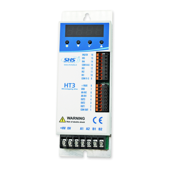
1.3 Inputs & Outputs Digital inputs and outputs pins are isolated from power Single Ended inputs IN1, IN2, IN3 compatible PNP input the common is COMIN_A pin. ● Single Ended inputs IN4, IN5, IN6 are NPN/PNP type selectable through COMIN_B pin. ●... - Page 6 2. CONNECTIONS 2.1 Input/Output connector SIGNAL FUNCTION Fieldbus + Fieldbus - GND_FB 0V Fieldbus 0V (+VCC, VREF, ANIN1,2, ANOUT) ANIN2 Analog input 2 ANIN1 Analog input 1 VREF Reference voltage output 10V ANOUT Analog output +VCC Auxiliary voltage output 15V IN6_EN Input 6 / ENABLE IN5_DIR...
-
Page 7: Enable Input
2.3 Enable Input To switch on the power of the motor must be connect a signal to Enable Input (IN6). Without this signal the drive stop the motor, there is not a deceleration ramp, and the motor phases current goes to zero. -
Page 8: Parameters Setting
3. SETTINGS 3.1 Parameters setting By using the buttons below the display (hereinafter referred to as [] , [▼], [▲] ,[ѵ]) you can parameterize the drive: To access to main menu, press [ѵ] per two seconds, it will visualize the first available parameter. ●... -
Page 9: Function Modes
4. FUNCTION MODES It is possible to set different function modes by the “Mode” parameter. Mode DESCRIPTION “ PD” Step/direction command “Modb” Modbus Fieldbus protocol “ Win” Winstar Fieldbus protocol “CanO” CanOpen Fieldbus protocol Basic Drive in Step Direction can’t have Mode option. Winstar and Modbus drive can have Step/direction mode. -
Page 10: Typical Application
4.1 Step Direction Mode “ PD” In Step/direction mode the drive execute a single step for each rising edge of the step-in signal IN4 step in clock (Maximum frequency 60KHz) IN5 defines the direction rotation. IN6 enable the drive. PARAMETERS Function Values Reset... - Page 11 4.2 Modbus Mode “MODB” The drive can support MODBUS-RTU protocol. It is possible to set Address, Baud-rate and Parity. Data format is N,8,1. PARAMETERS Function Values Reset 0par Reset Eeprom values Unaffected c urr Set the phase current [mA] See drive models table option 1000 baud BaudRate RS485[Kbps]...
-
Page 12: Register Table
4.3 Register table Tel. +39 0331 466918 Fax. +39 0331 466147 www.shsitalia.it S.H.S. s.r.l. Via F.lli Rosselli, 29 20027 Rescaldina (MI) – ITALY... - Page 13 Register table (cnt) Tel. +39 0331 466918 Fax. +39 0331 466147 www.shsitalia.it S.H.S. s.r.l. Via F.lli Rosselli, 29 20027 Rescaldina (MI) – ITALY...
- Page 14 4.4 Winstar Mode “ Uin” The drive can support WINSTAR proprietary protocol. It is possible to set Address, Baud-rate and Parity. Data format is N,8,1. PARAMETERS Function Values Reset 0par Reset Eeprom values Unaffected c urr Set the phase current [mA] See drive models table option 1000 baud...
-
Page 15: Command Table
4.5 Command table Tel. +39 0331 466918 Fax. +39 0331 466147 www.shsitalia.it S.H.S. s.r.l. Via F.lli Rosselli, 29 20027 Rescaldina (MI) – ITALY... - Page 16 Command table (cnt) Tel. +39 0331 466918 Fax. +39 0331 466147 www.shsitalia.it S.H.S. s.r.l. Via F.lli Rosselli, 29 20027 Rescaldina (MI) – ITALY...
- Page 17 Command table (cnt) Tel. +39 0331 466918 Fax. +39 0331 466147 www.shsitalia.it S.H.S. s.r.l. Via F.lli Rosselli, 29 20027 Rescaldina (MI) – ITALY...
- Page 18 Tel. +39 0331 466918 Fax. +39 0331 466147 www.shsitalia.it S.H.S. s.r.l. Via F.lli Rosselli, 29 20027 Rescaldina (MI) – ITALY...
- Page 19 Command table (cnt) Tel. +39 0331 466918 Fax. +39 0331 466147 www.shsitalia.it S.H.S. s.r.l. Via F.lli Rosselli, 29 20027 Rescaldina (MI) – ITALY...
-
Page 20: Special Version
SPECIAL VERSION: Dzz = Dedicate Software Szz = Modify Hardware (*) OPTION: View the following table FIELDBUS: WS = RS485 SHS Protocol MB = Modbus CO = CanOpen SIZE: 2 = 4A 20..28Vdc 3 = 4A 20..60Vdc 5 = 8A 20..60Vdc... - Page 21 Tel. +39 0331 466918 Fax. +39 0331 466147 www.shsitalia.it S.H.S. s.r.l. Via F.lli Rosselli, 29 20027 Rescaldina (MI) – ITALY...
Need help?
Do you have a question about the HT3 Series and is the answer not in the manual?
Questions and answers