
Subscribe to Our Youtube Channel
Related Manuals for SHS HT7 Series


Summary of Contents for SHS HT7 Series
- Page 1 User Guide STEPPING MOTOR DRIVE Series Models PROFINET HT7_PROFINET_rev8_eng Tel. +39 0331 466918 Fax. +39 0331 466147 www.shsitalia.it S.H.S. s.r.l. Via F.lli Rosselli, 29 20027 Rescaldina (MI) – ITALY...
-
Page 2: Safety Notes
The technicians must be able to recognize possible dangers that may result from programming, by changing parameter values and generally by the mechanical, electrical and electronic. SHS s.r.l. recommends to always follow basic safety rules. Failure to heed them can result in injury to persons and / or property. - Page 3 Index TECHNICAL DATA Power supply / Motor Connector FIELDBUS Connector Input/Output Connectors DIP-SWITCH and Ethernet Connectors Status LEDS Protection / Display messages Parameters setting Mechanical dimension CONNECTION Installation note AC Power Supply DC Power Supply Input / Outputs Digital Inputs Digital Outputs Encoder Inputs Analog Inputs/ Outputs...
-
Page 4: Technical Data
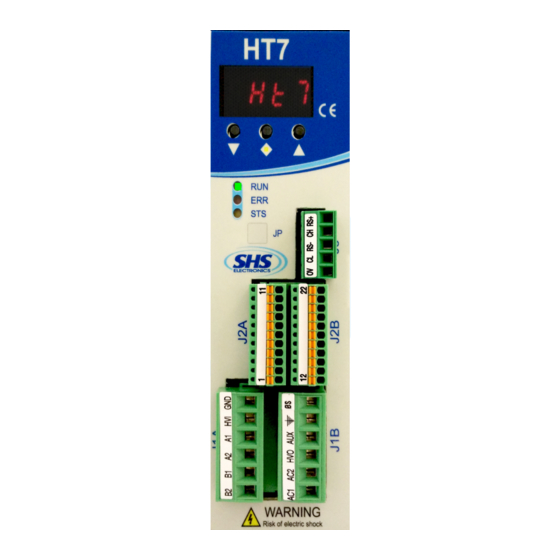
1. TECHNICAL DATA 1.1 Power supply / Motor connector J1A ( Left ) SIGNAL FUNCTION Phase B2 of the motor Phase B1 of the motor Phase A2 of the motor Phase A1 of the motor Power supply input DC (connect to HV0 or use as input DC power) 0V power supply J1B ( Right ) SIGNAL... -
Page 5: Input/Output Connectors
1.3 Input / Output Connectors J2A (Left) SIGNAL FUNCTION ENC_AH Encoder A+ ENC_AL Encoder A- ENC_BH Encoder B+ ENC_BL Encoder B- ENC_ZH Encoder Z+ ENC_ZL Encoder Z- Encoder common (don't se in differential ENC_COM mode) ENA/DIS Input ENABLE/DISABLE Input IN3 – (CURRENT REDUCTION) Input IN2 - (DIRECTION) Input IN1 –... -
Page 6: Dip Switch
1.4 DIP SWITCH DIP1 Insert termination CAN Not used Insert termination RS485 Not used Not used Not used Input function En / Dis = ENABLE Input function En / Dis = DISABLE Only HT7xx PN, EC, EI model is supplied of double RJ45 interface ( upper pictures ). The RJ45 connections can be used interchangeably in PN and EI model. - Page 7 1.6 Protection / Display messages DISPLAY DESCRIPTION Drive OK at STOP motor Motor in movement Drive DISABLE ocur Overcurrent Error tenP Overtemperature Error uuoL Undervoltage Error ouoL Overvoltage Error Reset phase 0net No connected Drive is provided with protections against overtemperature, overvoltage, undervoltage, short-circuits among outputs and among outputs and the positive power pole, no-phase motor connection.
-
Page 8: Parameters Setting
1.7 Parameters setting By using the buttons below the display (hereinafter referred to as [\/] , [<>], [/\] ) you can parameterize the drive: menu p001 To access to main menù, press [\/] + [<>] , it will visualized “ ”... -
Page 9: Mechanical Dimension
1.8 Mechanical dimension MODEL HT7 xx- WEIGHT [ gr ] WS-MB-CO-PB PN-EC-EI www.shsitalia.it info:shsbox@shsitalia.it... -
Page 10: Installation Notes
2. CONNECTIONS 2.1 INSTALLATION NOTES ATTENTION DANGER OF ELECTRICAL SHOCK ONLY QUALIFIED PERSONNEL SHOULD WORK ON THIS EQUIPMENT. DISCONNECT ALL POWER BEFORE WORKING ON EQUIPMENT. DANGEROUS VOLTAGES MAY EXIST AFTER POWER IS REMOVED! BEFORE WORKING ON EQUIPMENT CHECK DC BUS VOLTAGE OF DRIVES EACH TIME POWER IS REMOVED. -
Page 11: Wiring Diagram
WIRING DIAGRAM: In AC power mode do not connect GND signals between two or more HT7 drives: www.shsitalia.it info:shsbox@shsitalia.it... -
Page 12: Dc Power Supply
2.3 DC POWER SUPPLY Unit HT710 HT720 HT730 HT740 From 24 to Vac nom From 24 to 90 From 24 to 90 From 24 to 90 Vac max Vac min I max I min Operation [°C] 0 - 45 0 - 45 0 - 45 0 - 45 Temperature... - Page 13 2.4 Inputs / Outputs Digital inputs and outputs pins are isolated from power. Single Ended inputs are NPN/PNP type selectable through COM-IN pin. ● Differential input are TTL compatible, and can be 24V compatible PNP through COM-ENC pin. ● Outputs are NPN/PNP type selectable through COM-OUT (10mA max for OUT1, 100mA max for OUT2 and ●...
- Page 14 2.5 Digital Inputs 2.6 Digital Outputs www.shsitalia.it info:shsbox@shsitalia.it...
-
Page 15: Encoder Inputs
2.7 Encoder Inputs www.shsitalia.it info:shsbox@shsitalia.it... -
Page 16: Analog Inputs / Outputs
2.8 Analog Inputs / Outputs Note: we suggest to use isolated inputs scheme, no electrical connections between control and drives. 3. OPERATING MODE The driver can be operated in the follwing modes: PROFINET ● www.shsitalia.it info:shsbox@shsitalia.it... - Page 17 3.1 SETTING ON THE PROFINET MASTER Use the device master file “GSDML-v2,31-SHS-HT7-20160125.xml” to configure your communication software on the master. 3.2 DATA COMMUNICATION VIA PROFINET The data format used is Motorola (“Big Endian”). PROFINET structure: Protocol frame User data Protocol frame (Header) Parameter (PKW) –...
- Page 18 User data structure from SLAVE (HT7 drive) to MASTER: word word word (H) word (L) word word PKW: Parameter identifier value PZD: Process data PKE: Parameter idetifier IND: Index (not used) PWE: Parameter value STW: Status word 1 (see pag.16) HIW: Main actual value (not used) Parameter Identifier (PKE) (1st Word): The parameter identifier (PKE) is always a 16-bit value.
- Page 19 3.3 PROFINET CONTROL BITS BITS ZSW – MASTER SLAVE VALUE FUNCTION REMARKS 1 – ON ON - Start RELATIVE positioning This bit is ignored when absolute 0 - OFF OFF - Stop RELATIVE positioning positioning or JOG function is active 1 –...
- Page 20 BITS STW – SLAVE MASTER VALUE FUNCTION REMARKS 1 - ON ON - Drive ready 0 - OFF OFF - Drive fault or disable 1 - ON ON - Motor running 0 - OFF OFF - Motor stop 1 - ON ON - Drive disable 0 - OFF OFF - Drive enable...
-
Page 21: Relative Positioning
TA = time to START motor: maximum 30 ms TB = time between falling edge and rising edge of start signal: minimum 50 ms COMMAND SEQUENCE TO EXECUTE A POSITIONING: RELATIVE POSITIONING: - Enable driver (ZSW BIT 3) - Set relative quote (PNU 7) - Set start relative positioning bit (ZSW BIT 0) to 1 - Wait TA time to START motor (minimum 30ms) or front 0-1 of motor running bit (STW BIT 1) - Wait end of positioning (front 1-0) or zero level of motor running bit (STW BIT 1) - Page 22 HOMING: - Connect switch or proximity sensor (NO or NC) to IN1 - Enable driver (ZSW BIT 3) - Set maximum frequency - PNU 1 (in homing function it represents home search speed) - Set minimum frequency - PNU 0 (in homing function it represents sensor disengage speed) - Start homing (PNU 18) with a parameter 0x01 (HEX) for NC sensor or 0x11 (HEX) for NO sensor on IN1 Sensor not engaged: When you write PNU 18 the motor starts immediately in CCW direction with maximum speed, then it stops on sensor and starts in CW...
- Page 23 3.5 PARAMETERS FUNCTION PARAMETER Setting of minimum frequency From 1 to 10000 Hz Motor rotation start frequency Setting of maximum frequency From 1 to 20000 Hz Motor rotation working frequency Setting of ramp inclination From 1 to 255 expressed in ms * 10 If motor is running, this parameter will be acquired to the next motion command.
- Page 24 FUNCTION PARAMETER Setting of absolute quote From -2147483647 to 2147483647 Indicate the absolute positioning with respect to home position to be carried out at the next START (with control bit) or TRIGGER START expressed in 1/128 step Setting of home position From -2147483647 to 2147483647 Drive associates the entered value to home position of the motor Present position...
- Page 25 FUNCTION PARAMETER Trigger zerofly (logic AND) Use only less significant byte: It defines the input or the inputs and the respective levels, which must be enabled The 4 less significant bits indicate the input for carrying out zeroing of the value in the present motor position, when this or the inputs, which must be enabled for condition occurs, and the value to be done on occasion of this condition.
- Page 26 FUNCTION PARAMETER Protection active / reset If read = 0x00 drive ready = 0x02 short circuit = 0x04 thermal protection = 0x08 power supply undervoltage = 0x10 power supply overvoltage (in previous profibus versions in case of protection this value is set to 1) If write 0 reset permanent protection (short circuit or phase disconnected) the other...
-
Page 27: Special Version
SPECIAL VERSION: Dzz = Dedicate Software Szz = Modify Hardware (*) OPTION: View the following table FIELDBUS: WS = RS485 SHS Protocol MB = Modbus CO = CanOpen PB = Profibus PN = ProfiNet EC = EtherCat EI = Ethernet/IP... - Page 28 www.shsitalia.it info:shsbox@shsitalia.it...
- Page 29 Tel. +39 0331 466918 Fax. +39 0331 466147 www.shsitalia.it S.H.S. s.r.l. Via F.lli Rosselli, 29 20027 Rescaldina (MI) – ITALY...
Need help?
Do you have a question about the HT7 Series and is the answer not in the manual?
Questions and answers