
Subscribe to Our Youtube Channel
Related Manuals for SHS HT7 Series


Summary of Contents for SHS HT7 Series
- Page 1 User Guide STEPPING MOTOR DRIVE Series HW MANUAL HT7_HW_MANUAL_rev9_eng Tel. +39 0331 466918 Fax. +39 0331 466147 www.shsitalia.it S.H.S. s.r.l. Via F.lli Rosselli, 29 20027 Rescaldina (MI) – ITALY...
-
Page 2: Safety Notes
The technicians must be able to recognize possible dangers that may result from programming, by changing parameter values and generally by the mechanical, electrical and electronic. SHS s.r.l. recommends to always follow basic safety rules. Failure to heed them can result in injury to persons and / or property. - Page 3 Index TECHNICAL DATA Power supply / Motor Connector FIELDBUS Connector Input/Output Connectors DIP-SWITCH and Ethernet Connectors Status LEDS Protection / Display messages Parameters setting Mechanical dimension CONNECTION Installation note AC Power Supply DC Power Supply Input / Outputs Digital Inputs Digital Outputs Encoder Inputs Analog Inputs/ Outputs...
-
Page 4: Technical Data
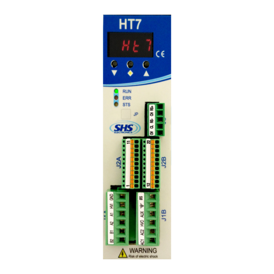
1. TECHNICAL DATA 1.1 Power supply / Motor connector J1A ( Left ) SIGNAL FUNCTION Phase B2 of the motor Phase B1 of the motor Phase A2 of the motor Phase A1 of the motor Power supply input DC (connect to HV0 or use as input DC power) 0V power supply J1B ( Right ) SIGNAL... -
Page 5: Input/Output Connectors
1.3 Input / Output Connectors J2A (Left) SIGNAL FUNCTION ENC_AH Encoder A+ ENC_AL Encoder A- ENC_BH Encoder B+ ENC_BL Encoder B- ENC_ZH Encoder Z+ ENC_ZL Encoder Z- Encoder common (don't use in differential ENC_COM mode) ENA/DIS Input ENABLE/DISABLE Input IN3 – (CURRENT REDUCTION) Input IN2 - (DIRECTION) Input IN1 –... -
Page 6: Dip Switch
1.4 DIP SWITCH DIP1 Insert termination CAN Not used Insert termination RS485 Not used Not used Not used Input function En / Dis = ENABLE Input function En / Dis = DISABLE Only HT7xx PN, EC, EI model is supplied of double RJ45 interface ( upper pictures ). The RJ45 connections can be used interchangeably in PN and EI model, in the EC model RJ45s have IN and OUT Phisical... - Page 7 1.6 Protection / Display messages DISPLAY DESCRIPTION Drive OK at STOP motor Motor in movement Drive DISABLE fieldbus HdIS Drive DISABLE Hardware (1) (2) ocur Overcurrent Error tenP Overtemperature Error uuoL Undervoltage Error ouoL Overvoltage Error Reset phase 0net Fieldbus not connected Encoder Fault Drive is provided with protections against overtemperature, overvoltage, undervoltage, short-circuits among outputs and among outputs and the positive power pole, no-phase motor connection.
-
Page 8: Parameters Setting
Enable refresh for the last polled parameter PN, EC, EI, MT p015 FieldBus Type and Firmware Release WS, MB, CO, PN, EC, EI, MT WS = RS485 SHS Protocol MB = Modbus CO = CanOpen PB = Profibus PN = ProfiNet... -
Page 9: Mechanical Dimension
1.8 Mechanical dimension MODEL HT7 xx- WEIGHT [ gr ] WS-MB-CO-PB PN-EC-EI www.shsitalia.it info:shsbox@shsitalia.it... -
Page 10: Installation Notes
2. CONNECTIONS 2.1 INSTALLATION NOTES ATTENTION DANGER OF ELECTRICAL SHOCK ONLY QUALIFIED PERSONNEL SHOULD WORK ON THIS EQUIPMENT. DISCONNECT ALL POWER BEFORE WORKING ON EQUIPMENT. DANGEROUS VOLTAGES MAY EXIST AFTER POWER IS REMOVED! BEFORE WORKING ON EQUIPMENT CHECK DC BUS VOLTAGE OF DRIVES EACH TIME POWER IS REMOVED. - Page 11 WIRING DIAGRAM: In AC power mode do not connect GND signals between two or more HT7 drives: www.shsitalia.it info:shsbox@shsitalia.it...
-
Page 12: Dc Power Supply
2.3 DC POWER SUPPLY Unit HT71H HT72H HT73H HT74H Vdc nom From 24 to 90 From 24 to 90 From 24 to 90 From 24 to 140 Vdc max Vdc min I max I min Operation [°C] 0 - 45 0 - 45 0 - 45 0 - 45... - Page 13 2.4 Inputs / Outputs Digital inputs and outputs pins are isolated from power. Single Ended inputs are NPN/PNP type selectable through COM-IN pin. ● Differential input are TTL compatible, and can be 24V compatible PNP through COM-ENC pin. ● Outputs are NPN/PNP type selectable through COM-OUT (10mA max for OUT1, 100mA max for OUT2 and ●...
- Page 14 2.5 Digital Inputs 2.6 Digital Outputs www.shsitalia.it info:shsbox@shsitalia.it...
-
Page 15: Encoder Inputs
2.7 Encoder Inputs www.shsitalia.it info:shsbox@shsitalia.it... -
Page 16: Analog Inputs / Outputs
Note: we suggest to use isolated inputs scheme, no electrical connections between control and drives. 3. OPERATING MODE The driver can be operated in one of the follwing modes: SHS RS485 PROTOCOL (WS) ● MODBUS RTU (MB) ● CAN OPEN (CO) ●... - Page 17 SPECIAL VERSION: Dzz = Dedicate Software Szz = Modify Hardware (*) OPTION: View the following table FIELDBUS: WS = RS485 SHS Protocol MB = Modbus CO = CanOpen PB = Profibus PN = ProfiNet EC = EtherCat EI = Ethernet/IP...
- Page 18 www.shsitalia.it info:shsbox@shsitalia.it...
- Page 19 Tel. +39 0331 466918 Fax. +39 0331 466147 www.shsitalia.it S.H.S. s.r.l. Via F.lli Rosselli, 29 20027 Rescaldina (MI) – ITALY...
Need help?
Do you have a question about the HT7 Series and is the answer not in the manual?
Questions and answers