
Subscribe to Our Youtube Channel
Related Manuals for SHS HT7 Series


Summary of Contents for SHS HT7 Series
- Page 1 User Guide STEPPING MOTOR DRIVE Series Models HT7_X Tel. +39 0331 466918 Fax. +39 0331 466147 www.shsitalia.it S.H.S. s.r.l. Via F.lli Rosselli, 29 20027 Rescaldina (MI) – ITALY...
- Page 2 Pay high attention, especially during installation and application development. Only use equipment properly sized for the application.. The SHS devices are considered components for automation and are sold as finished products to be installed only by qualified personnel and in accordance with all local safety regulations.
- Page 3 Index TECHNICAL DATA Power supply / Motor Connector FIELDBUS Connector Input/Output Connectors DIP-SWITCH and Ethernet Connectors Status LEDS Protection / Display messages Parameters setting Mechanical dimension CONNECTION Installation note AC Power Supply DC Power Supply Input / Outputs Digital Inputs Digital Outputs Encoder Inputs Analog Inputs/ Outputs...
-
Page 4: Technical Data
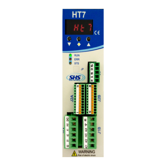
1. TECHNICAL DATA 1.1 Power supply / Motor connector J1A ( Left ) SIGNAL FUNCTION Phase B2 of the motor Phase B1 of the motor Phase A2 of the motor Phase A1 of the motor Power supply input DC ( connect to HV0 or use as input DC power ) 0V power supply J1B ( Right ) SIGNAL... -
Page 5: Input/Output Connectors
1.3 Input / Output Connectors J2A (Left) SIGNAL FUNCTION ENC_AH Encoder A+ ENC_AL Encoder A- ENC_BH Encoder B+ ENC_BL Encoder B- ENC_ZH Encoder Z+ ENC_ZL Encoder Z- ENC_COM Encoder common (don’t use in differential mode) ENA/DIS Input ENABLE/DISABLE Input IN3 - (CURRENT REDUCTION) Input IN2 - (DIRECTION) Input IN1 - (STEP IN) J2B (Right) -
Page 6: Dip Switch
1.4 DIP SWITCH DIP1 Insert termination CAN Not Insert termination CAN Insert termination RS485 Not Insert termination RS485 Not used Not used Input function En / Dis = ENABLE Input function En / Dis = DISABLE Only HT7xx_PN model is supplied of PROFINET interface ( upper right pictures ) The profiNET connections can be used interchangeably. - Page 7 1.6 Protection / Display messages DISPLAY DESCRIPTION Drive OK at STOP motor Motor in movement Drive DISABLE Overcurrent Error ocur Overtemperature Error tenP Undervoltage Error uuoL Overvoltage Error ouoL A Phase motor Error Ph1o B Phase motor Error Ph2o Reset phase Drive is provided with protections against overtemperature, overvoltage, undervoltage, short-circuits among outputs and among outputs and the positive power pole, no-phase motor connection.
-
Page 8: Parameters Setting
Reserved parameter for diagnostic p012 Setting serial parity ( n, e, o ) p013 NOTE: For settings PROFINET parameters refer to attach Legend MODE: ST = Step/Direction WS = RS485 SHS Protocol MB = Modbus CO = CanOpen www.shsitalia.it info:shsbox@shsitalia.it... -
Page 9: Mechanical Dimension
1.8 Mechanical dimension Model HT7xx- Weight [ gr ] WS-MB-CO-PB PN-EC www.shsitalia.it info:shsbox@shsitalia.it... -
Page 10: Installation Notes
2. CONNECTIONS 2.1 INSTALLATION NOTES ATTENTION DANGER OF ELECTRICAL SHOCK ONLY QUALIFIED PERSONNEL SHOULD WORK ON THIS EQUIPMENT. DISCONNECT ALL POWER BEFORE WORKING ON EQUIPMENT. DANGEROUS VOLTAGES MAY EXIST AFTER POWER IS REMOVED! BEFORE WORKING ON EQUIPMENT CHECK DC BUS VOLTAGE OF DRIVES EACH TIME POWER IS REMOVED. - Page 11 In AC power mode do not connect GND signals between two or more HT7 drives: www.shsitalia.it info:shsbox@shsitalia.it...
-
Page 12: Dc Power Supply
2.3 DC POWER SUPPLY Unit HT710 HT720 HT730 HT740 Vdc nom From 24 to 90 From 24 to 90 From 24 to 90 From 24 to 125 Vdc max Vdc min Operating [°C] 0 - 45 0 - 45 0 - 45 0 - 45 temperature Vdc aux (*) - Page 13 2.4 Inputs / Outputs Digital inputs and outputs pins are isolated from power. Single Ended inputs are NPN/PNP type selectable through COM-IN pin. ● Differential input are TTL compatible, and can be 24V compatible PNP through COM-ENC pin. ● Outputs are NPN/PNP type selectable through COM-OUT (10mA max for OUT1, 100mA max for OUT2 and ●...
- Page 14 2.5 Digital Inputs 2.6 Digital Outputs www.shsitalia.it info:shsbox@shsitalia.it...
-
Page 15: Encoder Inputs
2.7 Encoder Inputs www.shsitalia.it info:shsbox@shsitalia.it... -
Page 16: Analog Inputs / Outputs
2.8 Analog Inputs / Outputs Note: we suggest to use isolated inputs scheme, no electrical connections between control and drives. 2.9 FIELDBUS Interface The drives are supplied with half duplex RS485 and CAN interface. The FIELDBUS is isolated from the power stage. To enable different protocols must be loaded different firmware. - Page 17 To change the use mode use the keyboard and change the p002 parameter. When the operating mode is changed, restart the drive. Note: In SHS PROTOCOL and MODBUS mode, the drive can be use in Step/Direction mode. 3.1 Step/Direction Mode...
- Page 18 Outputs: SIGNAL FUNCTION OUT1 STEP OUT (J2B-2) Toggle every step-in DRIVER-READY OUT2 Drive in protection: OUT2 OFF (J2B-3) Drive ready : OUT2 ON OUT3 Unused (J2B-4) www.shsitalia.it info:shsbox@shsitalia.it...
- Page 19 HT7xxKK - yyyyy / Zzz SPECIAL VERSION: Dzz = Dedicate Software Szz = Modify Hardware (* OPTION View the following table FIELDBUS WS = RS485 SHS Protocol MB = Modbus CO = CanOpen PB = Profibus PN = ProfiNet EC = EtherCa SIZE 10 = 4A 18..60Vac o 24..90Vdc...
- Page 20 Tel. +39 0331 466918 Fax. +39 0331 466147 www.shsitalia.it S.H.S. s.r.l. Via F.lli Rosselli, 29 20027 Rescaldina (MI) – ITALY...
Need help?
Do you have a question about the HT7 Series and is the answer not in the manual?
Questions and answers