Advertisement
Available languages
Available languages
Quick Links
STEPPING MOTOR DRIVE
S.H.S. s.r.l. Via F.lli Rosselli, 29 20027 Rescaldina (MI) – ITALY
HT3
- User manual -
Italiano
English
[Rev. 1.04 – F222 / F522]
Series
Azienda con sistema di gestione certificato
Company Quality Assurance conforming
Tel. +39 0331 466918 Fax. +39 0331 466147 www.shsitalia.it
Advertisement

Subscribe to Our Youtube Channel
Related Manuals for SHS HT3 Series


Summary of Contents for SHS HT3 Series
- Page 1 Series STEPPING MOTOR DRIVE - User manual - Italiano English [Rev. 1.04 – F222 / F522] Azienda con sistema di gestione certificato Company Quality Assurance conforming Tel. +39 0331 466918 Fax. +39 0331 466147 www.shsitalia.it S.H.S. s.r.l. Via F.lli Rosselli, 29 20027 Rescaldina (MI) – ITALY...
- Page 2 • SHS s.r.l. non è responsabile di danni a cose e/o persone causati da installazioni errate e/o da modifiche non autorizzate del prodotto. I sistemi di comando danneggiati non devono essere montati o messi in funzione, onde evitare lesioni a persone e danni a cose.
- Page 3 Azienda con sistema di gestione certificato Company Quality Assurance conforming Indice CARATTERISTICHE TECNICHE Note di installazione Alimentazione DC Ingressi e Uscite CONNESSIONI Connettore ingressi / uscite Connettore alimentazione / motore IMPOSTAZIONI Impostazione parametri Messaggi display MODALITA' DI FUNZIONAMENTO Modalità STEP/DIR Modalità...
- Page 4 Azienda con sistema di gestione certificato Company Quality Assurance conforming 1. CARATTERISTICHE TECNICHE 1.1 Note di installazione ATTENZIONE Pericolo di scosse elettriche. Solo persone qualificate possono il maneggiare il dispositivo. Controllare i terminali di alimentazione dell’azionamento ogni volta che viene tolta tensione prima di lavorare sul dispositivo.
- Page 5 Azienda con sistema di gestione certificato Company Quality Assurance conforming 1.3 Ingressi e uscite Caratteristiche dei segnali: (IN1, IN2, IN3, ENABLE) LIVELLO DI TENSIONE BASSO LIVELLO DA 0 A 4V ALTO LIVELLO DA 7 A 24V CORRENTE MAX 13 mA USCITE LIVELLO DI TENSIONE USCITA ON...
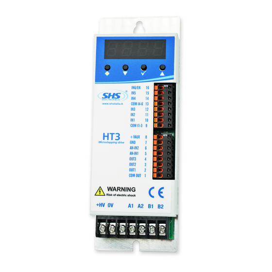
- Page 6 Azienda con sistema di gestione certificato Company Quality Assurance conforming Connessioni 2.1 Connettore ingressi / uscite SEGNALE FUNZIONE IN6/ENAB Ingresso 6 / ENABLE Ingresso 5 Ingresso 4 COM I4...I6 Comune ingressi 4, 5, 6 Ingresso 3 Ingresso 2 Ingresso 1 COM I1...I3 Comune ingressi 1, 2, 3 +VAUX...
- Page 7 Azienda con sistema di gestione certificato Company Quality Assurance conforming 2.3 Collegamento Enable Nella normale modalità di funzionamento, il segnale sul morsetto ENABLE (IN6) deve essere sempre attivo. Con segnale ENABLE non attivo l'azionamento ferma il motore, senza rampa di decelerazione, togliendo corrente alle fasi.
- Page 8 Azienda con sistema di gestione certificato Company Quality Assurance conforming 3. IMPOSTAZIONI 3.1 Impostazione parametri Tramite in tasti sotto il display (di seguito indicati con [],[],[],[v] ) è possibile parametrizzare l'azionamento: Selezionare il parametro da modificare ruotando il selettore []. Verrà visualizzato il titolo relativo al ●...
- Page 9 Azienda con sistema di gestione certificato Company Quality Assurance conforming 4. MODALITA' DI FUNZIONAMENTO E' possibile impostare le diverse modalità di funzionamento tramite il parametro “Func”. Di seguito vengono descritte le caratteristiche, i parametri e l'associazione degli ingressi e delle uscite per ciascuna modalità.
- Page 10 Azienda con sistema di gestione certificato Company Quality Assurance conforming 4.1 Modalità “ STEP / DIR ” L'azionamento esegue un micropasso ad ogni fronte del segnale STEP (IN4), nella direzione definita dal segnale DIR (IN3). PARAMETRI Funzione Valori Func Impostazione della modalità di funzionamento Impostazione della direzione del motore 0=Diretta 1=Invertita Curr...
- Page 11 Azienda con sistema di gestione certificato Company Quality Assurance conforming 4.2 Modalità “ SPEED MODE ” Al fronte di salita del segnale di START (IN1), l'azionamento fa partire il motore in rampa fino alla velocità regolata dall'ingresso analogico SPEED (AN-IN1) e nella direzione definita dal segnale DIR (IN3). L'ingresso analogico SPEED (AN-IN1) definisce in ogni momento la velocità...
- Page 12 Azienda con sistema di gestione certificato Company Quality Assurance conforming 4.3 Modalità “ ETICHETTATRICE ” (*) Sequenza etichettatura: 1 - Dal fronte di salita del segnale di START (IN1), trascorso il tempo “ritardo pistone” (ms) viene attivata l'uscita PISTONE (OUT1) 2 - Trascorso il tempo “ritardo di start”...
- Page 13 Azienda con sistema di gestione certificato Company Quality Assurance conforming 5. INTERFACCIA SERIALE 5.1 Protocollo “ MODBUS ” (*) Nel modello con interfaccia seriale RS485 è possibile leggere e scrivere i registri interni tramite il protocollo MODBUS-RTU. Indirizzo e baud-rate sono impostabili tramite il pannello. Il formato dei dati è...
- Page 14 Azienda con sistema di gestione certificato Company Quality Assurance conforming 5.2 Tabella registri REGISTRI REGISTRO NOME Unità ACCESSO FORMATO PROM RANGE DIAG vedi descr. UINT 0 ÷ 65535 FIRMWARE VERSION vedi descr. 0xF000 ÷ 0xFFFF PASSWORD 0÷9999 UINT 0 ÷ 9999 FUNC vedi descr.
- Page 15 Azienda con sistema di gestione certificato Company Quality Assurance conforming 0 - DIAGNOSTICA VALORE DESCRIZIONE 0x0000 Drive ready, motore fermo 0x8000 Drive ready, motore RUN 0x8001 Errore generico 0x8002 Disable 0x8003 Errore Over Current 1 - FIRMWARE VERSION [ 15 ÷ 12 ] [ 11 ÷...
- Page 16 Azienda con sistema di gestione certificato Company Quality Assurance conforming 7 – STEP Impostazione del microstepping VALORE DESCRIZIONE FULL STEP 1 / 2 STEP 1 / 4 STEP 1 / 8 STEP 1 / 16 STEP 8 – CURRENT DESCRIZIONE Impostazione della corrente di fase del motore, espressa in mA.
- Page 17 Azienda con sistema di gestione certificato Company Quality Assurance conforming 25 – SETTINGS OPERAZIONE DESCRIZIONE Abilita finecorsa 0=finecorsa disabilitati 1=finecorsa abilitati 1 ÷ 15 Riservati 26 - SPD ATTUALE DESCRIZIONE Fornisce la velocità attuale del motore espressa in RPM. 27 - I/O OUT3 OUT2 OUT1 28 –...
- Page 18 • SHS s.r.l. is not responsible for damages to things and / or persons caused by incorrect installations and / or modifications not authorized by the product. Damaged control systems must not be mounted or put into operation to avoid injury people and damage to things.
- Page 19 Index TECNICAL CHARACTERISTICS Installation notes DC power supply Inputs & Ouputs CONNECTIONS Input/Output connector Power supply / motor connector SETTINGS Parameters setting Display messages FUNCTION MODES STEP/DIRmode SPEED mode LABELLER mode SERIAL INTERFACE MODBUS protocol Tel. +39 0331 466918 Fax. +39 0331 466147 www.shsitalia.it S.H.S.
- Page 20 1. TECNICAL CHARACTERISTICS 1.1 Installation notes ATTENTION Danger of electric shock. Only qualified persons can handle the device. Check the drive power terminals whenever voltage is removed before working on the device. 1.2 DC power supply Unit HT320 HT350 Vdc nom Vdc max Vdc min phase max...
- Page 21 1.3 Inputs & Outputs Signals characteristics: (IN1, IN2, IN3, ENABLE) VOLTAGE LEVEL LOW LEVEL 0 to 4V HIGH LEVEL 7 to 24V MAX CURRENT 13 mA OUTPUTS LIVELLO DI TENSIONE COM_OUT VOLTAGE - 2V PNP OUTPUT NPN OUTPUT COM_OUT VOLTAGE ANALOG INPUTS VALUE MEASURE RANGE...
- Page 22 Connections 2.1 Input/Output connector SIGNAL FUNCTION IN6/ENAB Input 6 / ENABLE Input 5 Input 4 COM I4...I6 Inputs 4, 5, 6 common ref. Input 3 Input 2 Input 1 COM I1...I3 Inputs 1, 2, 3 common ref. +VAUX Auxiliary voltage output +10.5 Vdc 0V (VAUX, AN-IN1, AN-IN2) AN-IN2 Analog input 2...
- Page 23 3. IMPOSTAZIONI 3.1 Parameters setting Using the push buttons near the display (following as [],[],[],[v] ) it is possible to set the parameters of the drive. Select the parameter to modify by pressing [] to visualize the correct parameter. ● To visualize the current value of the parameter, press [v].
- Page 24 4. FUNCTION MODES It is possible to set different function modes by the “Func” parameter. Following characteristics, parameters and input/output association for each function mode FUNCTION DESCRIPTION Command by Modbus protocol * Reserved Reserved Step/dir command SPEED mode control ( Start/Stop + DIR ) SPEED mode control ( Start + Stop + DIR ) SPEED mode control ( Start/Stop CW + Start/Stop CCW ) Labeller **...
- Page 25 4.1 “ STEP / DIR ” mode The drive execute a single microstep for each front of the STEP (IN4) signal, in direction defined by the DIR (IN3 signal. PARAMEERS Function Values Func Set of function mode Set of the direction of the motor 0=Direct 1=Reverse Curr Set of the phase current [mA]...
- Page 26 4.2 “ SPEED ” mode To the uprising front of the START (IN1 or IN2) signal, the drive will start the motor with a ramp to the speed set to the SPEED (AN-IN1) analog input, and in the direction defined to the DIR (IN3) signal. The SPEED (AN-IN1) analog signal defines in every time the target speed for the motot, proportional to the maximum speed set in the relative parameter (10V →...
- Page 27 4.3 “ LABELLER ” mode (*) Labelling sequence: 1 – From the START (IN1) signal, after the “Piston delay” time (ms), the PISTON (OUT1) output will be activated 2 – After the “Start delay” time (ms) the drive starts the label erogation to the speed regulated by the SPEED (AN- IN1) analog input.
- Page 28 5. SERIAL INTERFACE 5.1 “ MODBUS ” protocol (*) With the model with RS485 serial interface it is possible to read and write the internal registers by the MODBUS- RTU protocol. It is possible to set Address and baud-rate by the panel. Data format is N,8,1.
- Page 29 Azienda con sistema di gestione certificato Company Quality Assurance conforming 5.2 Register table REGISTRI REGISTER NAME Unit ACCESS FORMAT PROM RANGE DIAG see descr. UINT 0 ÷ 65535 FIRMWARE VERSION see descr. 0xF000 ÷ 0xFFFF PASSWORD 0÷9999 UINT 0 ÷ 9999 FUNC see descr.
- Page 30 Azienda con sistema di gestione certificato Company Quality Assurance conforming 0 – DIAGNOSTIC VALUE DESCRIPTION 0x0000 Drive ready, motore stop 0x8000 Drive ready, motore RUN 0x8001 Generic error 0x8002 Disable 0x8003 Over Current error 1 - FIRMWARE VERSION [ 15 ÷ 12 ] [ 11 ÷...
- Page 31 Azienda con sistema di gestione certificato Company Quality Assurance conforming 7 – STEP Set of microstepping VALORE DESCRIZIONE FULL STEP 1 / 2 STEP 1 / 4 STEP 1 / 8 STEP 1 / 16 STEP 8 – CURRENT DESCRIPTION Motor phase current,set in mA.
- Page 32 Azienda con sistema di gestione certificato Company Quality Assurance conforming 25 – SETTINGS OPERATIONE DESCRIPTION Enable limit sensors 0=limit sensors disabled 1=limit sensors enabled 1 ÷ 15 Riservati 26 – ACTUAL SPD DESCRIPTION Read the actual speed of the motor in RPM. 27 - I/O OUT3 OUT2 OUT1 28 –...
- Page 33 Tel. +39 0331 466918 Fax. +39 0331 466147 www.shsitalia.it S.H.S. s.r.l. Via F.lli Rosselli, 29 20027 Rescaldina (MI) – ITALY...
Need help?
Do you have a question about the HT3 Series and is the answer not in the manual?
Questions and answers